


7
Chapter 7 Location and Function of Parts and Controls 97HDC-900/950/930 Series Product Information Manual
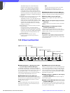
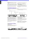
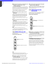
a SD output block (DIF board) 1 SD SDI OUT 1 and
SD SDI OUT 2 (SD-SDI output 1 and 2)
connectors (BNC type)
When the system is operating with the field frequency
of 59.94/50 Hz, the signals from the video camera may
be down-converted to SD-component SDI signals and
output from these connectors. The OUT 2 connector
can be assigned for a digital monitor output that
includes character and marker information.
b PIX OUT (picture monitor output) connector
(BNC type)
Used for output of the picture monitor video signal
selected using the RCP-700-series Remote Control
Panel MONITOR SELECT button or the MSU-700A/
750 Master Setup Unit PICTURE MONITOR button.
(When both the RCP and MSU are in use, this
connector functions as the output connector for RCP
control.)
c WF OUT (waveform monitor output) connector
(BNC type)
Used for output of the video signal for waveform
monitoring selected using the RCP-700-series Remote
Control Panel’s MONITOR SELECT button or the MSU-
700A/750 Master Setup Unit’s WF MONITOR button.
(When both the RCP and MSU are in use, this
connector functions as the output connector for RCP
control.)
Note
The SC phase of the VBS signal output from
connectors 2 and 3 is not locked to the black burst
signal supplied to the REFERENCE connector. Use the
vector monitor in Internal Sync mode.
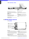
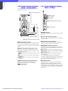
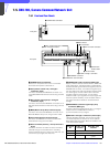
7-4-4 HKCU-951 SD Encoder Unit
The optional HKCU-951 is to be installed in the HDCU-
950 expansion slot.
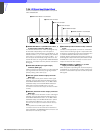
Connector panel (VDA board)
Note
All the connectors function when the system is
operated at a 59.94-/50-Hz field frequency, but do not
operate when the system field frequency is 60 Hz.
a VBS OUT (composite video signal output)
connector (BNC type)
Used for output of the video camera signal in analog
composite video format. An internal setting enables
the SD SDI OUT1 and OUT2 connectors on the DIF
board also to be used as analog VBS outputs.
b Y/G, B-Y/B, and R-Y/R (component video signal
output) connectors (BNC type)
Used for output of either Y, B-Y, R-Y component video
signals or G, B, R component video signals. The type
of signal is selected using switches on the EN board.
(Factory setting: G, B, R)
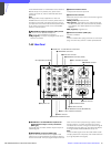
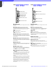
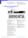
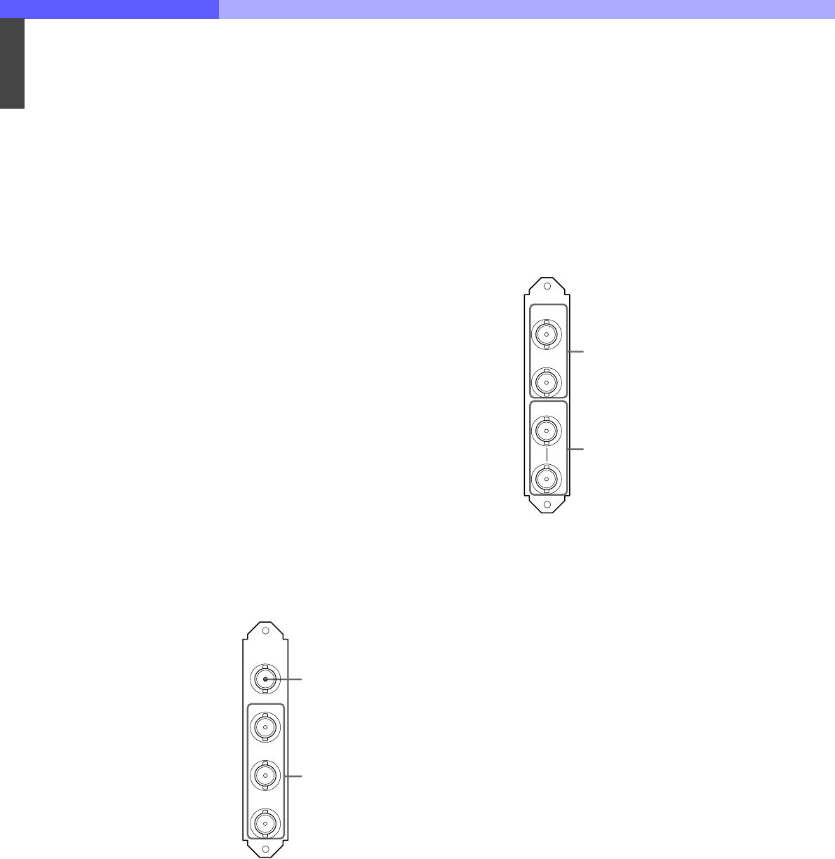
7-4-5 HKCU-953 HD Frame Rate
Converter Unit
The optional HKCU-953 is to be installed in the slot for
the DIF board (SD output block)/internal RC board
after moving them to the expansion slot.
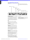
Connector panel (SDI board)
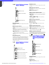
a HD SDI OUT 1 and HD SDI OUT 2 (HD SDI output
1 and 2) connectors (BNC type)
These connectors output the signals from the camera
as HD-SDI signals. When the camera is operating in
24PsF mode, frame conversion can be applied to input
signals to provide 60i/50i signals from these
connectors.
b FRAME REF IN and OUT (frame reference input
and output) connectors (BNC type)
The IN connector is used to receive an HD tri-level
reference sync signal or SD reference sync signal
(black burst signal) for frame sequence lock between
camera control units. The signal supplied to the IN
connector is output from the OUT connector as-is.
When this unit is used as the master unit, the OUT
connector can be used as the frame sync pulse output
connector for pull down.
EN
VBS
OUT
Y/G
B-Y/B
R-Y/R
1 VBS OUT connector
2 Y/G, B-Y/B, and R-Y/R connectors
FC
HD SDI
OUT 1
HD SDI
OUT 2
FRAME
REF IN
OUT
1 HD SDI OUT 1 and HD SDI OUT 2
connectors
2 FRAME REF IN and OUT connectors