


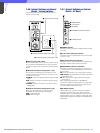
7
Chapter 7 Location and Function of Parts and Controls 106HDC-900/950/930 Series Product Information Manual
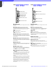
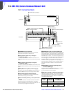
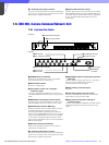
waveform monitor to the WF A OUTPUT loop connector
on the VCS-700 which is the last unit in the series
connection.
k WF B OUTPUT (waveform monitor B output)
connector (BNC type)
Supplies the same video signal for a waveform monitor
as the WF A OUTPUT connector. The signal loss of a
connecting cable up to 100 meters (330 feet) long can
be compensated for with the switch on the internal
board. When you connect a waveform monitor using a
long connecting cable, connect it to this connector.
When using two or more VCS-700 units connected in
series, connect a waveform monitor to the PIX B
OUTPUT connector on the VCS-700 whose WF A
OUTPUT loop connector is not used for series
connection. For details on cable compensation, refer
to the system manual.
l WF MODE (waveform monitor mode) connector
(4-pin)
Connect to a corresponding connector on a waveform
monitor to view the signals in sequential mode. This
connector supplies a staircase signal and sequential
ON/OFF control signal.
m REMOTE connector (8-pin)
Connect a CNU-700 Camera Command Network Unit
using a CCA-5 cable.
n I/O PORT (remote control) connector (D-sub 37-
pin)
Accepts and supplies external control signals. You
can select the signals output to a picture monitor and
a waveform monitor with an external video selector
connected to this connector. The selected input
connector number is supplied from this connector.
o ~AC IN (AC power input) connector
Connect to an AC power source using the supplied AC
power cord. The power cord can be fixed to the VCS-
700 using the supplied plug holder.
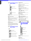
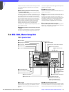
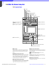
7-8. MSU-700A, Master Setup Unit
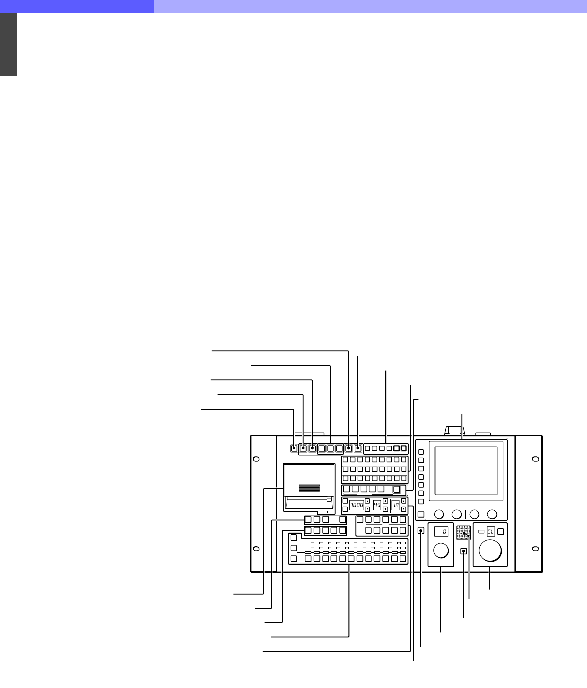
7-8-1 Operation Panel
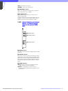
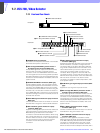
a ALL button
Press the button so it starts flashing to activate the 13
buttons located at the right (from CAM PW to AUTO
SETUP) for all the connected cameras of the same
group.
b CAM PW (camera power) button
Press and light up this button to turn the power supply
to the video camera ON. (The button promptly flashes
until the camera becomes ready for transmission.)
1
123456789101112
2345
12345
ABCDE
RGB
ENC
RGB
SEQ ENC
ON
ECS
AUTO SETUP
MODE
KNEE
OFF
DETAIL
OFF
LVLDEP
OFF
GAMMA
OFF
CHROMA
OFF
SKIN DTL
AUTO HUE
LEVEL
ALL CLOSE STANDARD
CAM PW
VF PW TEST1 TEST2 BARS
START/
BREAK
WHITE BLACK
MULTI
CARD
CONFIGURATION
MAINTENANCE
FILE
PAINT
MATRIX
OFF
KNEE
APARTURE
KNEE
SAT
MONO
COLOR
COLOR
CORRECT
5600K AUTO
KNEE
SKIN
DETAIL
DETAIL
GATE
SATURATION
CONTRAST
CHARACTER
BLACK
GAMMA
ECS/SHUTTER
PICTURE MONITOR
ACCESS
PARA
PANEL
ACTIVE
EXPAND
WAVEFORM MONITOR
ND
CC
FILTER CTRL
MULTI
TALLY
STORE
SCENE FILES
GAMMA
MASTER GAIN
MASTER BLACK IRIS
IRIS/MB
ACTIVE
CALL
AUTO
EXT
1 ALL button
2 CAM PW button
3 VF PW button
4 Signal output select buttons
5 CLOSE button
6 STANDARD button
7 AUTO SETUP block
8 Camera/CCU function ON/OFF buttons
9 Scene file control block
q; Menu operation block
qa IC card insertion block
qs PICTURE MONITOR buttons
qd WAVEFORM MONITOR buttons
qf Camera select block
qg Filter control block
qh ECS/Shutter control block (left)
Gamma control block (center)
Master gain control block (right)
qj IRIS/MB ACTIVE button
qk MASTER BLACK control block
ql CALL button
w; Camera number/
tally indication window
wa Iris control block