


7
Chapter 7 Location and Function of Parts and Controls 101HDC-900/950/930 Series Product Information Manual
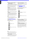
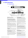
SYNC: To adjust the sync level
CHROMA: To adjust the chroma level
c COMPONENT controls
Each is for adjusting the corresponding component
video output (R/R-Y, G/Y, or B/B-Y).
d SC PHASE switch
Used to adjust the SC phase with respect to the
reference signal (BB).
This switch will return to its original position when you
release it. Press and hold the switch toward ADV to
advance the phase or toward DELAY for delay.
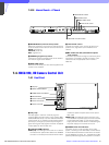
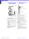
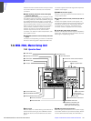
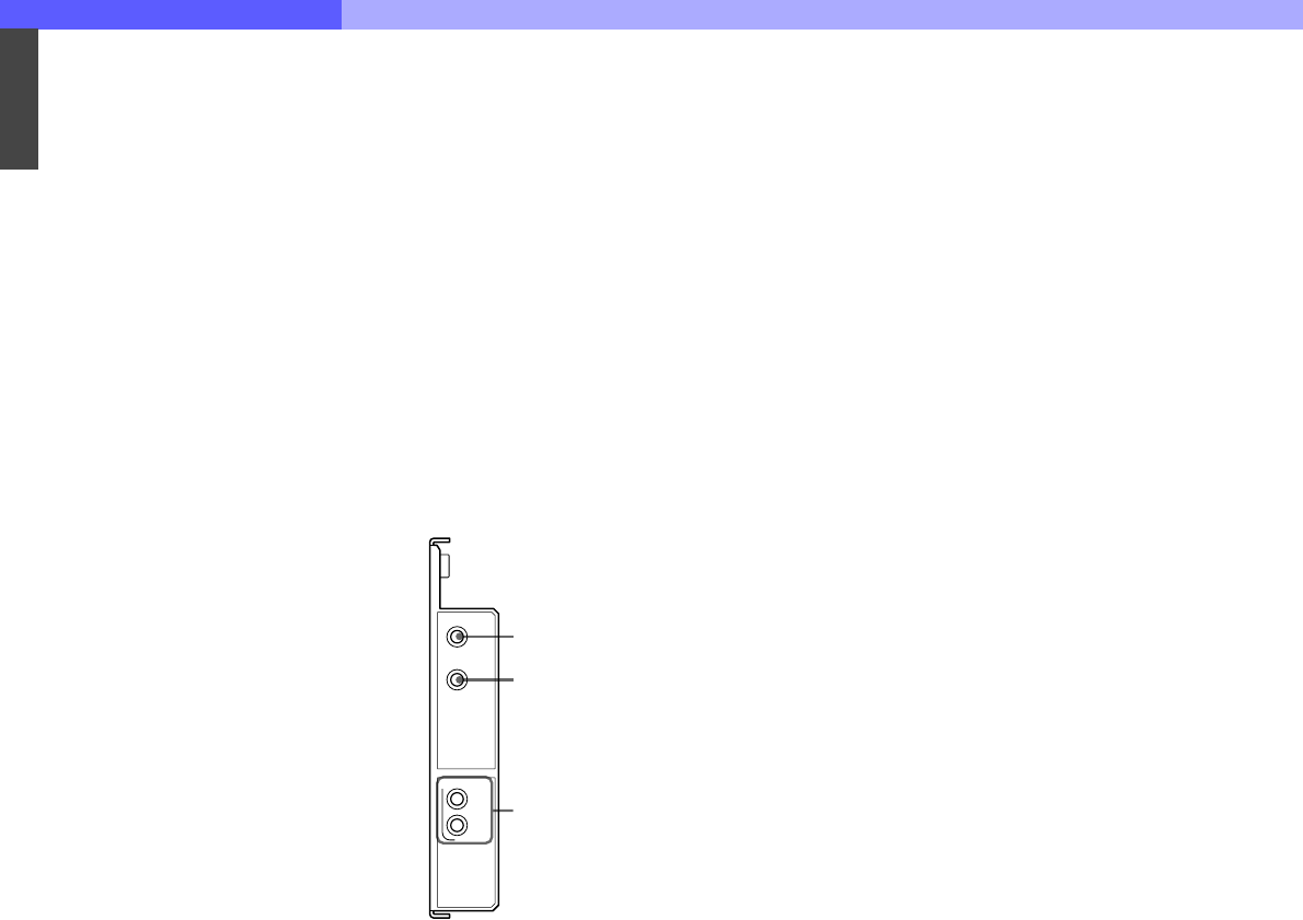
7-4-13 Internal Switches and Internal
Boards – FC Board (Internal
board of the optional HKCU-
953)
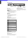
a POWER indicator
The LED is lit when the power voltage inside the board
is normal.
b CONVERT indicator
The LED is lit when the camera is operating in 24PsF
mode and the HKCU-953 is supplying 60i/50i signals
after frame conversion. It goes dark when the HKCU-
953 is supplying the input 24PsF signals as-is or when
the camera is operating in 60i, 50i, 30PsF, or 25PsF
mode.
c FRAME indicators
REF IN: The LED is lit when a subsidiary reference
signal for frame lock is being supplied.
UNLOCK: The LED lights if correct lock to the
subsidiary reference signal being supplied cannot
be achieved.
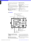
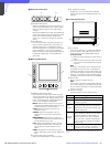
FC
POWER
FRAME
CONVERT
REF IN
UN
LOCK
1 POWER indicator
2 CONVERT indicator
3 FRAME indicators