


7
Chapter 7 Location and Function of Parts and Controls 141HDC-900/950/930 Series Product Information Manual
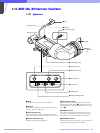
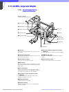
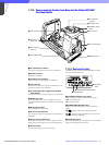
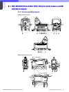
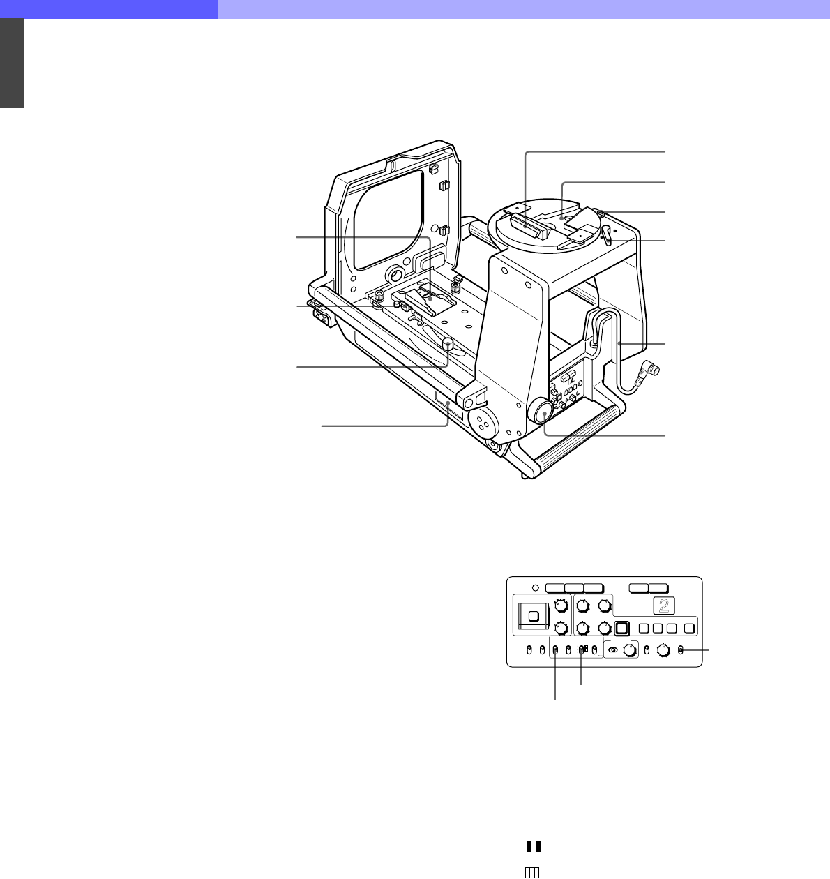
7-17-2 Camera-mounting Section (Inner Base) and the Optional BKP-9057
Viewfinder Saddle
a VF (viewfinder) connector
Connect to the camera connector on a viewfinder.
b Viewfinder mount
Attach the viewfinder.
c Viewfinder release button
Push this button to disengage the viewfinder
d Pan-lock lever
Turn counterclockwise to tighten the viewfinder. Turn
clockwise to loosen the viewfinder.
e VF connecting cable (supplied with the BKP-
9057) (20-pin)
Connects to the VF connector (20-pin) on the camera.
f Saddle lock knob
Locks the saddle so it does not topple down. Turn
counterclockwise to tighten the saddle, or clockwise to
loosen it.
g Number plate holder
Fit the supplied number plates.
h Camera mount slide lever
Pull this lever to slide the camera mount forward and
backward.
i Camera mount release lever
To remove the camera from the unit, push this lever
while pushing the safety lever (on the left) rightward.
j Camera mount
Fit the camera. Slide to the front and rear.
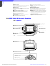
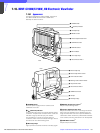
7-17-3 Rear control panel
CA-905L (during use with the HDC-950/930 only) with
rear-panel sticker attached
a VF SCAN (viewfinder scan) switch
Selects the aspect ratio of the viewfinder screen.
16:9: 16:9 aspect ratio
4:3: 4:3 aspect ratio
b SCREEN SIZE MARKER switch
Selects the screen size marker on the viewfinder
screen.
ON ( ): Display area is bounded by two dark
margins.
ON( ): Display area is bounded by two white lines.
OFF: No marker is displayed.
c Assignable switch
A function specified by menu setting on the HDC-950/
930 can be assigned to this switch.
1 VF (viewfinder)
connector
2 Viewfinder mount
3 Viewfinder release
button
4 Pan-lock lever
5 VF connecting cable
6 Saddle lock knob
7 Number plate holder
8 Camera mount
slide lever
9 Camera mount
release lever
q; Camera mount
3 H-POSI
POWER
WIDTH
V-POSI
HEIGHT STORE
CORSOR
ND
FILTER LOCAL
CC
VF DETAIL
ON
OFF
ENTERCANCEL
2
1
4
5
C
B
A
D
E
RGB RET RET 1
1 2 3 ON
DISPLAY MENU SELECT
ON
OFF
MENU
UP
TALLY
SCREEN
SIZE
MARKER
ON
OFF OFF
VF
SCAN
16:9
ON
4:3
SAFETY
ZONE
ON
OFF
CENTER
MARKER
ON
OFF
1 VF SCAN switch
2 SCREEN SIZE MARKER switch
3 Assignable
switch