


7
Chapter 7 Location and Function of Parts and Controls 90HDC-900/950/930 Series Product Information Manual
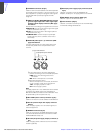
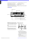
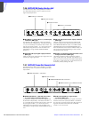
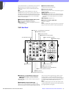
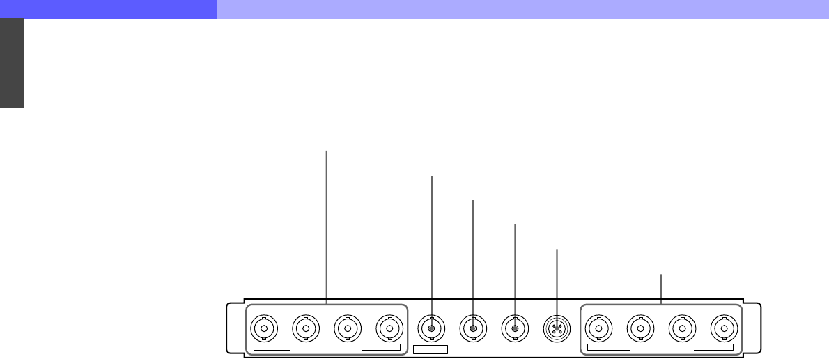
7-3-4 SD Signal Input/Output Block
These connectors can be replaced with the optional
HKCU-902/903/904.
a SERIAL RET INPUT 1-4 (SD-SDI return video 1, 2,
3, and 4 input) connectors (BNC type)
Four different SD-SDI return video input signals may
be received independently when the system is
operating with the field frequency of 59.94/50 Hz. The
selection of RET 1, 2, 3, or 4 is made by the camera’s
return switch. The type of input signal on RET 1, 2, 3,
and 4 may be set individually using switches on the
internal AT board, or using the MSU-700A/750 Master
Setup Unit. The aspect ratio may also be selected for
SD signals.
b SYNC OUT (HD/SD sync signal output)
connector (BNC type)
Used for output of an HD tri-level sync or SD composite
sync signal from the internal sync signal generator.
(Factory setting: HD tri-level sync)
c PIX OUT (picture monitor output) connector
(BNC type)
Used for output of the picture monitor video signal
selected using the RCP-700 series Remote Control
Panel MONITOR SELECT button, or the MSU-700A/
750 Master Setup Unit PICTURE MONITOR button.
(When both the RCP and MSU are in use, this
connector functions as the output connector for RCP
control.)
d WF OUT (waveform monitor output) connector
(BNC type)
Used for output of the waveform monitor video signal
selected using the RCP-700-series Remote Control
Panel MONITOR SELECT button, or the MSU-700A/
750 Master Setup Unit WF MONITOR button. (When
both the RCP and MSU are in use, this connector
functions as the output connector for RCP control.)
Note
The SC phase of the VBS signal output from
connectors 3 and 4 is not locked to the black burst
signal supplied to the REFERENCE IN connector. Use
the monitor in Internal sync mode.
e WF MODE (waveform monitor mode) connector
(4-pin)
Connect to the appropriate connector on a waveform
monitor when monitoring a signal in sequential mode.
A sequence signal will be output when the SEQ button
on the RCP-700 series Remote Control Panel is
pressed, allowing simultaneous monitoring of the R, G,
and B signals in sequential mode. (When both the RCP
and MSU are in use, this connector functions as the
output connector for RCP control.)
f SERIAL OUTPUT 1-4 (SD-SDI 1, 2, 3, and 4
output) connectors (BNC type)
When the system is operating with the field frequency
of 59.94/50 Hz, the signal from the video camera may
be down converted and output as four SD component
SDI signals.
SYNC OUT PIX OUT WF OUT
1234 1234
SERIAL RET INPUT SERIAL OUTPUT
WF MODE
1 SERIAL RET INPUT 1-4 connectors
2 SYNC OUT connector
3 PIX OUT connector
4 WF OUT connector
5 WF MODE connector
6 SERIAL OUTPUT 1-4 connectors