


7
Chapter 7 Location and Function of Parts and Controls 111HDC-900/950/930 Series Product Information Manual
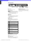
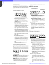
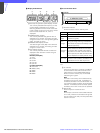
C AUTO button
Press and light the button to automatically adjust
the iris according to the amount of input light
(Auto Iris). If you press the button when lit, it
goes dark and manual iris adjustment is
enabled.
Note
If the subject being used as the reference for
automatic adjustment is lost while operating a
camera having the skin tone auto iris function,
the skin tone auto iris stops functioning, and the
iris value at that time is maintained. The AUTO
button then flashes. In this condition, not only is
the iris not automatically adjusted but also it
cannot be changed manually. When you wish to
change the iris, turn Auto Iris off. If Auto Iris is
kept ON, the skin tone auto iris will start
functioning when the subject for reference is
resumed.
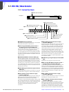
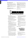
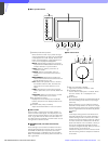
7-8-2 Operation Panel in use with HD
Equipment
Camera/CCU function ON/OFF buttons
When this unit is used in an HD camera system (HDC-
700/750/700A/750A/900/950/930, HDW-700/F900,
HDCU-700/900/950), another three camera/CCU
function ON/OFF buttons become effective. Use the
unit with the labels for an HD system (supplied)
attached to the appropriate positions.
Right two buttons in the upper row (OFF when the
button is lit)
SD MATRIX OFF: To turn on/off the linear matrix in
down converting
SD DETAIL OFF: To turn on/off the SD contour
compensation function in down converting
Fourth button from the left in the middle row (ON
when the button is lit)
LOW KEY SAT: To turn on/off the low key saturation
function (linear matrix for dark areas)
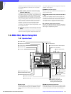
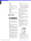
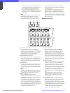
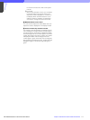
Menu operation block/1 MODE (mode select)
buttons
The uppermost MODE button in the menu operation
block functions as the FUNCTION button both in HD
and SD camera systems. Use the unit with the supplied
label attached as shown below.
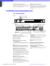
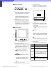
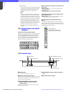
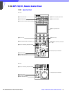
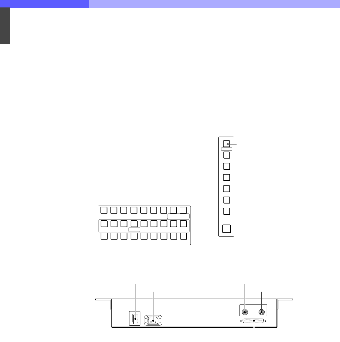
7-8-3 Connector Panel
a POWER switch
Turns on and off the power of this unit.
b AC IN (AC power input) connector
Connect to an AC power source using an optional AC
power cord. The power cord can be fixed to this unit
using an optional plug retainer.
c CCU/CNU REMOTE (camera control unit/
camera command network unit remote)
connector (8-pin)
Connect to the RCP/CNU connector of CCU or the
MSU connector of CNU.
d AUX REMOTE (auxiliary remote) connector (8-
pin)
e I/O PORT connector (50-pin)
KNEE
OFF
DETAIL
OFF
LVLDEP
OFF
GAMMA
OFF
CHROMA
OFF
MATRIX
OFF
KNEE
APERTURE
KNEE
SAT
MONO
COLOR
COLOR
CORRECT
5600K AUTO
KNEE
SKIN
DETAIL
DETAIL
GATE
SATURATION
CONTRAST
CHARACTERBLACK
GAMMA
SD MATRIX
OFF
SD DETAIL
OFF
LOW KEY
SAT
MODE
MULTI
CARD
CONFIG
MAINTENANCE
FILE
PAINT
FUNCTION
FUNCTION buttons:
Selects Function menu to control
various camera and CCU functions.
POWER
I
O
I/O PORT
AUX
CCU/CNU
REMOTE
AC IN
1 POWER switch
2 AC IN connector
3 CCU/CNU REMOTE connector
4 AUX REMOTE connector
5 I/O PORT connector