


8
Chapter 8 Connectors and Cables 144HDC-900/950/930 Series Product Information Manual
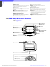
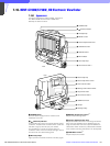
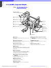
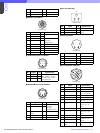
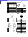
HKC-T950 Connector Layout
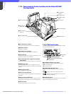
Input/Output Signals
a CCU connector
Based upon BTA S-004A/005A/006A 1.485 Gbps
serial
Output Signals
b EARPHONE OUT (HDC-950/930)
EARPHONE mini jack
c TEST OUT
BNC type 75 Ohms, 1.0 V p-p
d PROMPTER OUT *
BNC type 75 Ohms, 1.0 V p-p
e HD SERIAL DIGITAL OUT
Based upon BTA-S004A
BNC type 75 Ohms, 0.8 V p-p 1.485 Gbps
w; VIDEO OUT (HKC-T950)
BNC type 75 Ohms, 1.0 V p-p
Input Signals
4 GENLOCK IN* (HDC-950/930)
BNC type 75 Ohms, 1.0 V p-p
4 RET IN* (HDC-950/930)
BNC type 75 Ohms, 1.0 V p-p
f Not used
* Use this connector by selecting PROMPTER OUT,
GENLOCK IN and RET IN signals with the switch on the rear
panel of the HDC-950/930.
PROMPTER OUT signal becomes effective when the camera
is connected to the CCU.
GENLOCK IN and RET IN signals become effective when the
camera is used alone.
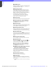
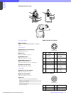
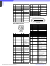
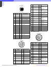
g RET CONTROL (6P FEMALE)
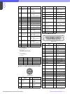
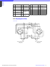
h DC OUT (4P FEMALE)
wa
wd
wa
ws
wg
ws
wf
w;
qg
wd
No. Signal I/O Specifications
1 INCOM 1
MIC ON/OFF
IN Zi ≥ 10 kOhms
ON : GND
OFF : OPEN
2 INCOM 2
MIC ON/OFF
IN Zi ≥ 10 kOhms
ON : GND
OFF: OPEN
3GND —
4 NC — No connection
5 RET 1 ON/OFF IN Zi ≥ 10 kOhms
ON : GND
OFF : OPEN
6 RET 2 ON/OFF IN Zi ≥ 10 kOhms
ON : GND
OFF : OPEN
No. Signal I/O Specifications
1 GND — GND for POWER
2 NC No connection
(External view)
1
23
4
(External view)