


7
Chapter 7 Location and Function of Parts and Controls 89HDC-900/950/930 Series Product Information Manual
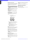
750 Master Setup Unit or RCP-700 series
Remote Control Panel. Either a recall-type
monitor, or the 1730HD/1735HD Waveform
Monitor, may be connected. When using a
recall-type monitor, preset a display mode on
the waveform monitor, and then recall the mode
externally. Switches on the AT board are used to
select either recall type or 1730HD/1735HD type
operation.
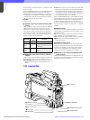
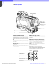
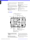
C TRUNK LINE connector (D-sub 9-pin, RS- 232C)
Used to connect the HDCU-900 to the
TRACKER connector on an HDC-900 HD Color
Video Camera via an RS-232C interface. Used
mainly for communication with equipment on the
camera side. The RXD, TXD, RTS, and CTS
signals can be transferred at up to 19.2 kbps
using this connector.
D MIC REMOTE (microphone remote) connector
(D-sub 15-pin)
Using this connector, the video camera’s
microphone input level may be set by external
equipment such as an audio mixer, in five steps
(–60, –50, –40, –30, and –20 dB). When taping,
set the volume to a level appropriate for the
audio conditions.
E I/O PORT connector (D-sub 15-pin)
Used for remote control using an external
control device.
Note
Use of a case wider than 42 mm can cause
interference at connectors 2, 4, 5. It is
recommended to use JAE-made DA-C1-J10.
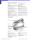
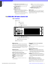
d CHARACTER OUTPUT connector (BNC type)
Used to output the results of the HDCU-900 diagnostic
self-test in SD black and white analog video format.
e DIGITAL AUDIO connector (BNC type)
Used to output a digital audio signal input to the
camera.
f MIC OUTPUT (microphone output) connectors
(XLR 3-pin)
Used for output of the microphone input to the video
camera.
g INTERCOM/TALLY/PGM (program audio)
connector (D-sub 25-pin)
Used for input and output of intercom, tally, and
program audio signals. Connect to the intercom/tally/
program audio connector of the intercom system.
h Expansion slot
For installation of the optional HKCU-901 SD Analog
Interface Unit, HKCU-902 HD Analog Interface Unit,
HKCU-903 Frame Rate Converter Unit, or HKCU-904
Line Converter Unit.
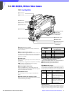
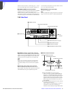
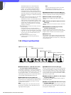
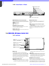
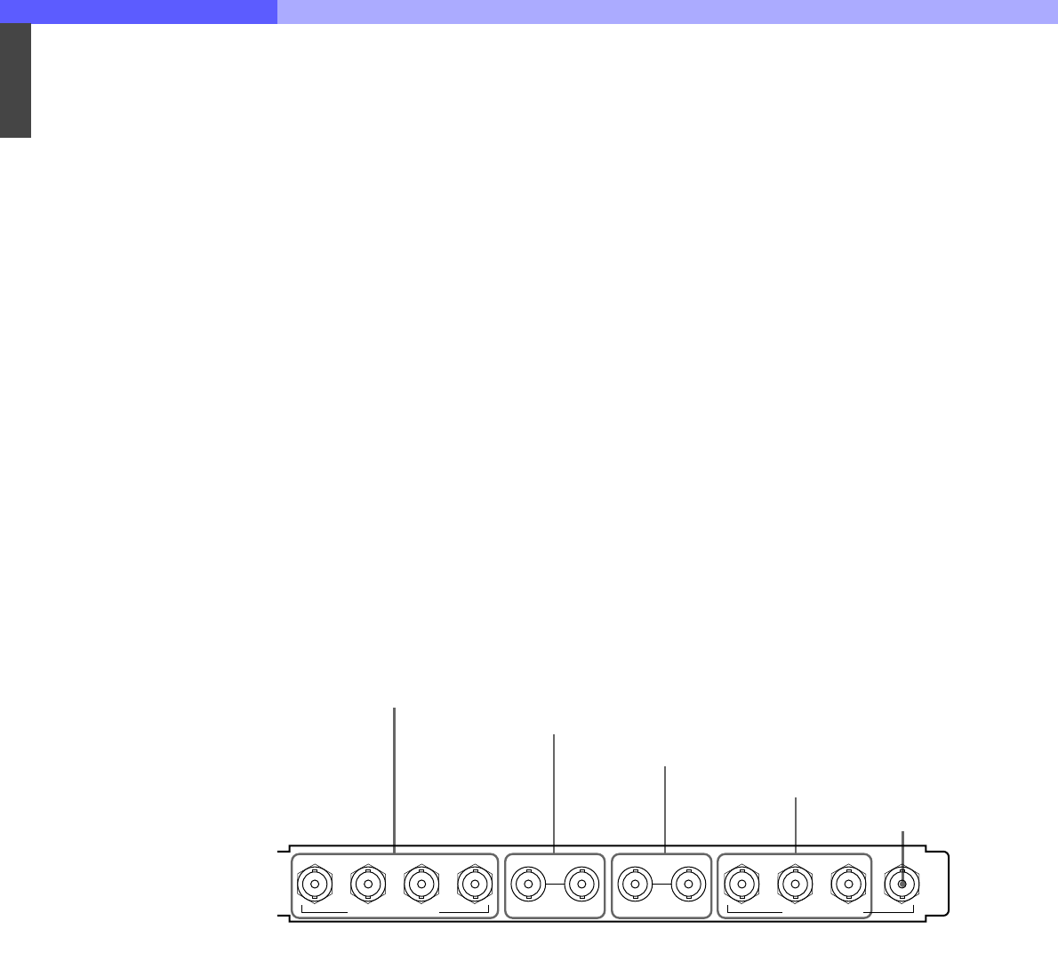
7-3-3 HD Signal Input/Output Block
a SERIAL RET INPUT 1-4 (HD-SDI return video 1,
2, 3, and 4 input) connectors (BNC type)
Four different HD-SDI return video input signals may
be received independently. The selection of RET 1, 2,
3, or 4 is made by the camera’s return switch. The type
of input signal on RET 1, 2, 3, and 4 may be set
individually using switches on the internal AT board, or
using the MSU-700A/750 Master Setup Unit.
b REFERENCE IN connectors (BNC type)
Used to input an HD tri-level reference sync signal or
SD reference sync signal (black burst signal). If loop-
through output is not used, terminate the unused
connector with 75 ohms.
Note
To use the VBS signal of the HKCU-901 (when SC
phase lock is required), use an SD reference sync
signal (black burst signal).
c PROMPTER IN connectors (BNC type)
Used for prompter signal input. If loop-through output
is not used, terminate the unused connector with 75
ohms. If the signal used is a 1.0 Vp-p, 75-ohm signal,
it may be output from the video camera PROMPTER
OUT connector with a frequency bandwidth of 8 MHz,
regardless of signal format.
d SERIAL OUTPUT 1-3 (HD-SDI 1, 2, and 3 output)
connectors (BNC type)
The signal from the video camera may be output as
three HD-SDI signals.
e SERIAL OUTPUT MONI (HD-SDI monitor output)
connector (BNC type)
The signal from the video camera may be mixed with
skin tone gate signals and some aspect marker signal
and output in HD-SDI format.
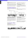
1 SERIAL RET INPUT 1-4 connectors
2 REFERENCE IN connectors
3 PROMPTER IN connectors
4 SERIAL OUTPUT 1-3 connectors
5 SERIAL OUTPUT MONI
connector
1234 1 2 3 MONI
SERIAL RET INPUT REFERENCE IN PROMPTER IN SERIAL OUTPUT