


7
Chapter 7 Location and Function of Parts and Controls 80HDC-900/950/930 Series Product Information Manual
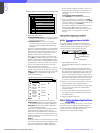
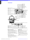
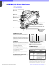
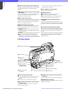
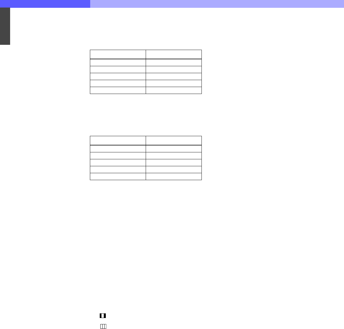
c ND filter selector
When the FILTER LOCAL button is lit up, this selector
may be used to select an ND filter.
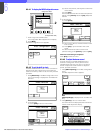
d CC (color temperature conversion) filter
selector
When the FILTER LOCAL button is lit up, this selector
may be used to select a color temperature conversion
filter appropriate to the light source illuminating the
subject.
e FILTER LOCAL (filter local control) button
Pressing this button enables selection of a color
temperature conversion filter or ND filter using the CC
filter selector and ND filter selector. Pressing the
button again gives control of the filters to the MSU-
700A/750 Master Setup Unit or RCP-700 series
Remote Control Panel.
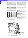
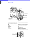
f UP TALLY switch
Set whether or not the camera’s Up Tally lamp and the
lens’ tally lamp will light when the camera receives a
red tally signal.
ON: The tally lamps will light.
OFF: The tally lamps will not light.
g VF (viewfinder) SCAN switch
Used to control the viewfinder screen display.
16:9: To set the viewfinder display to 16:9 aspect ratio.
4:3: To set the viewfinder display to 4:3 aspect ratio.
h SCREEN SIZE MARKER switch
Used to control the display of the screen size marker
as follows:
ON ( ): Areas outside the specified ratio area will be
darkened.
ON ( ): The screen size marker (white lines) will be
displayed.
OFF: The screen size marker will not be displayed.
i CENTER MARKER switch
Used to control the display of the center marker as
follows:
ON: A marker indicating the center of the picture area
will be displayed on the viewfinder screen. The
position of the center marker may be adjusted for
the lens being used. The adjusted position may be
stored in a lens file.
OFF: The center marker will not be displayed.
j SAFETY ZONE switch
Used to control the display of the safety zone marker
as follows:
ON: A frame marking 90% of the picture area (the
safety zone) will be displayed on the viewfinder
screen. Using the Marker Settings page in the
Operation menu, the size of the displayed frame
may also be set to 80%, 92.5%, or 95% of the picture
area.
OFF: The safety zone will not be displayed.
k DISPLAY switch
The functions of the DISPLAY switch are as follows:
ON: Text and messages describing the camera
settings and operating status may be displayed on
the viewfinder screen.
OFF: Status messages will not appear on the
viewfinder screen.
MENU: Menus for camera settings will be displayed on
the viewfinder screen.
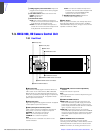
l MENU SELECT switch
The functions of the MENU SELECT switch are as
follows:
ENTER: Confirm the menu or page selected using the
MENU SELECT control, or confirm setting values.
CANCEL: Cancel menu setting values or return to
page select mode or the top menu.
m MENU SELECT control
Used to select menu items or change setting values in
the menus displayed on the viewfinder screen.
n Assignable switch
You can assign a function, such as lens extender ON/
OFF, using the OPERATION menu.
o VF DETAIL (viewfinder detail adjustment) switch
ON: Emphasizes the contours of the image on the
viewfinder screen. When the switch is set to this
position, you can adjust the amount of detail using
the VF DETAIL control.
OFF: Disables contour emphasis.
p VF DETAIL (viewfinder detail) control
Adjust the amount of detail of the picture on the
viewfinder screen when the VF DETAIL switch is set to
ON. This has no effect on the output signal of the
camera.
Note
The viewfinder detail control function has no effect on
a return video signal.
q CALL button
• Press to call the operator of the HDCU-900 Camera
Control Unit, the MSU-700A/750 Master Setup Unit,
or the RCP-700 series Remote Control Panel. When
pressed, the camera’s red tally lamp will light up if
previously off, and turn off if previously on. The CALL
button on the MSU-700A/750 Master Setup Unit or
RCP-700 series Remote Control Panel will light up,
and their buzzer will sound.
• When the CALL button on the RCP-700 series
Remote Control Panel or the MSU-700A/750 is
pressed, this button will light up.
r CURSOR (cursor memory) 1, 2, and 3 buttons
Used to store the size and position of the box cursor
displayed on the viewfinder screen. Three different
box cursor settings may be stored in memory using
buttons 1, 2, and 3. Pressing one of these buttons will
cause a cursor of the stored size to be displayed in the
stored position.
Note
When one of the CURSOR buttons is lit up, the HPOSI,
V-POSI, WIDTH, and HEIGHT buttons will be disabled.
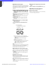
Selector position Selected filter
1 Clear
21/4ND
31/8ND
41/16ND
51/64ND
Selector position Selected filter
ACross filter
B 3200K (clear)
C 4300K
D 6300K
E 8000K