


7
Chapter 7 Location and Function of Parts and Controls 92HDC-900/950/930 Series Product Information Manual
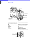
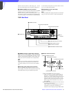
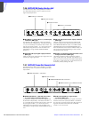
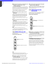
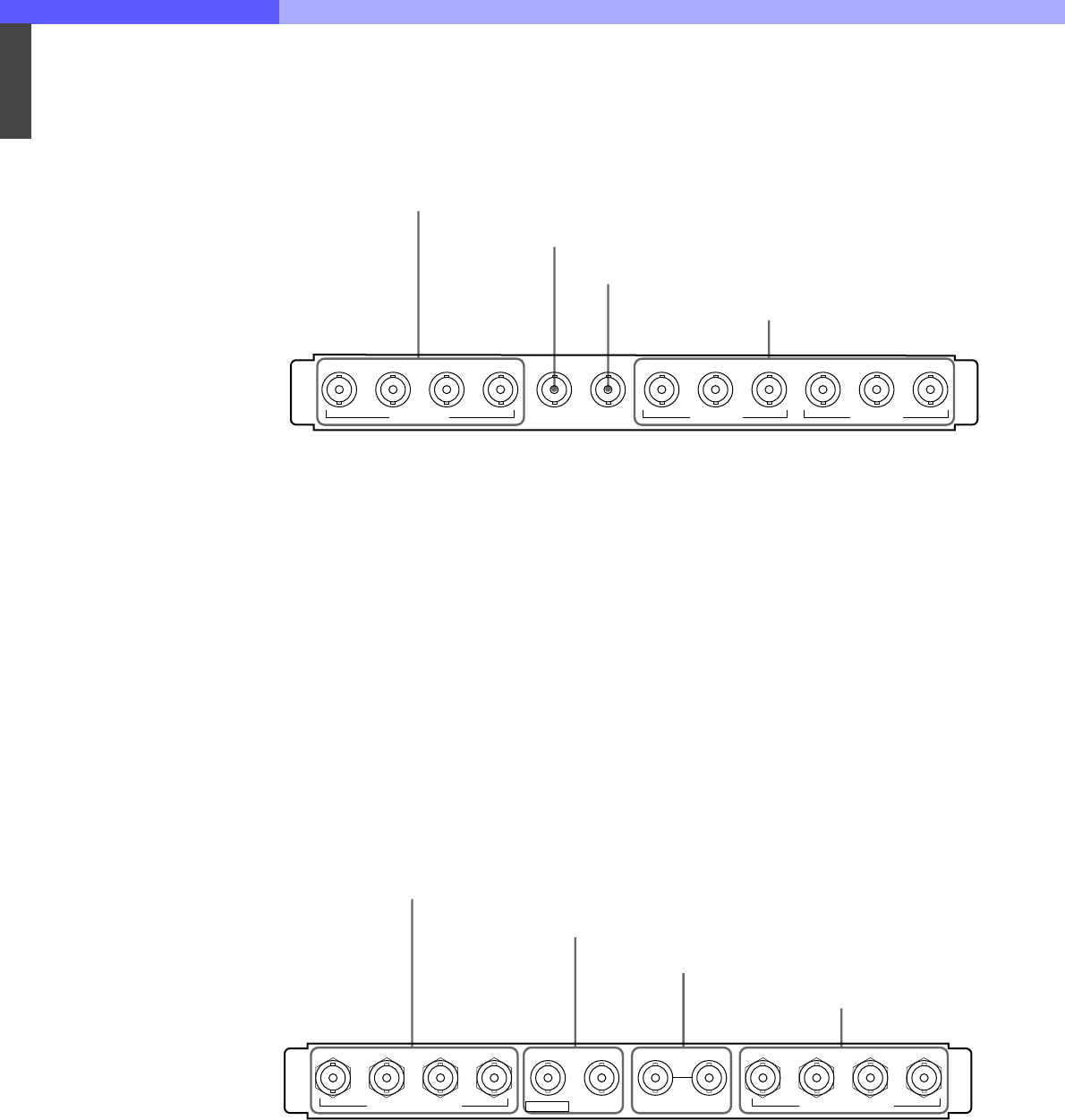
7-3-6 HKCU-902 HD Analog Interface Unit
The optional HKCU-902 is designed to be installed in
the HDCU-900 expansion slot or in place of the SD
signal input/output block.
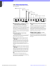
a RET INPUT 1-4 (return video 1, 2, 3, and 4 input)
connectors (BNC type)
Four different HD analog return video input signals
may be received independently. The selection of RET
1, 2, 3, or 4 is made by the camera’s return switch. The
type of input signal on RET 1, 2, 3, and 4 may be set
individually using switches on the AT board in the
HDCU-900, or using the MSU-700A/750 Master
Setup Unit.
b SYNC OUT (HD sync signal output) connector
(BNC type)
Used for output of an HD tri-level sync signal from the
internal sync signal generator.
c PIX OUT (HD picture monitor output) connector
(BNC type)
Used for output of the picture monitor video signal
selected using the RCP-700 series Remote Control
Panel MONITOR SELECT button, or the MSU-700A/
750 Master Setup Unit PICTURE MONITOR button.
Either the Remote Control Panel or Master Setup Unit
may control the output, depending on which button
was pressed most recently.
d OUTPUT 1, 2 (HD analog component video 1 and
2 output) connectors (BNC type)
HD analog component video signals are output in
either Y, PB, PR or G, B, R format. The selection of Y,
PB, PR or G, B, R format may be made independently
for OUTPUT 1 and OUTPUT 2, using switches on the
AT board. (Factory setting: G, B, R)
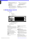
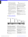
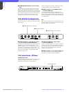
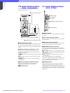
7-3-7 HKCU-903 Frame Rate Converter Unit
The optional HKCU-903 is to be installed in the HDCU-
900 expansion slot or in place of the SD signal input/
output block.
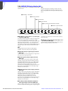
a SERIAL RET INPUT 1-4 (HD-SDI return video 1,
2, 3, and 4 input) connectors (BNC type)
Four different HD-SDI return video input signals may
be received independently. The selection of RET 1, 2,
3, or 4 is made by the camera’s return switch. The type
of input signal on RET 1, 2, 3, and 4 may be set
individually using switches on the AT board in the
HDCU-900, or using the MSU-700A/750 Master Setup
Unit.
b SYNC OUT (HD/SD sync signal output)
connectors (BNC type)
The left connector outputs a sync signal of the same
format as that of the input/output block in the above
slot. The right connector outputs the HD tri-level sync
signal of the same format as that of the SERIAL
OUTPUT 1 to 3 connectors.
1234
RET INPUT
PIX OUTSYNC OUT
OUTPUT 1
PR/R
OUTPUT 2
Y/G PB/B PR/RY/G PB/B
1 RET INPUT 1-4 connectors
2 SYNC OUT connector
3 PIX OUT connector
4 OUTPUT 1, 2 connectors
1234 1 2 3 MONI
SERIAL RET INPUT
SYNC OUTSYNC OUT FRAME REFERENCE
SERIAL OUTPUT
IN OUT
1 SERIAL RET INPUT 1-4 connectors
2 SYNC OUT connectors
3 FRAME REFERENCE IN/OUT connectors
4 SERIAL OUTPUT 1 to 3 and MONI connectors