


7
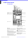
Chapter 7 Location and Function of Parts and Controls 108HDC-900/950/930 Series Product Information Manual
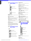
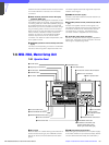
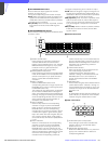
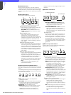
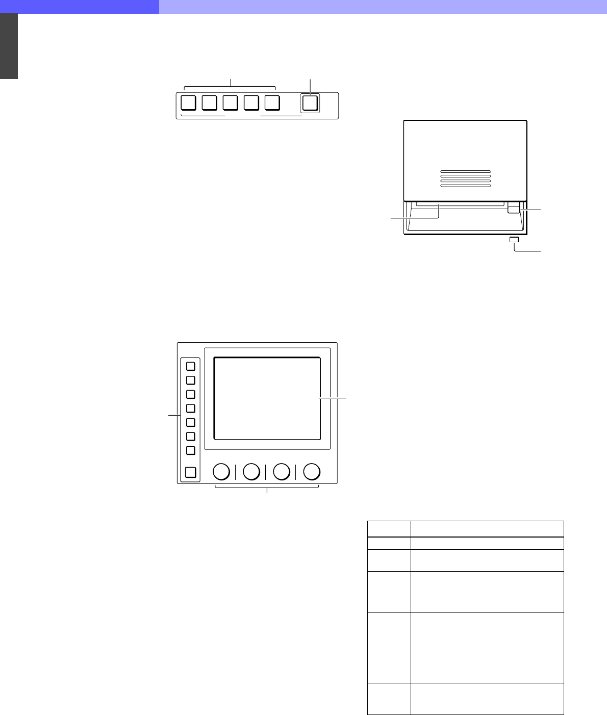
i Scene file control block
A SCENE FILES buttons
While the STORE button is flashing: When you
press one of these buttons, the current setting
data is stored as a file of the corresponding
number.
When the STORE button is dark: The stored data
can be retrieved by pressing and lighting up the
button of the desired number. Press the lit
button to turn it dark and resume the previous
status.
B STORE button
To store a scene file, first press this button so
that the button starts flashing, then press the
SCENE FILES button of the desired number.
When file registration is completed, the STORE
button goes dark. To cancel the registration,
press the flashing button again before pressing
the SCENE FILES button. The STORE button
goes dark.
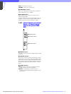
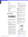
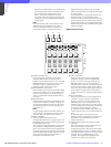
j Menu operation block
A MODE (mode select) buttons
Select the menu mode. If you press and light
one of these buttons, the menu for the selected
mode appears on the EL display. When the lit
button is pressed again, it goes dark and the
menu on the display also disappears.
MULTI: Selects Multi-Control menu to set the
requirements for Master/Slave mode to set up
multiple cameras in synchronization.
CARD: Selects IC memory card menu to
initialize IC cards.
CONFIG: Selects Configuration menu to
configure this unit and the entire camera
system.
MAINTENANCE: Maintenance mode to set
various camera maintenance items and the H
and SC phases of CCU, etc.
FILE: Selects File operation menu to retrieve
and transfer reference files, lens files and
scene files in the video camera or on IC
cards.
PAINT: Selects Paint control menu to adjust
various paint items, such as white, black and
flare.
B Control knobs (rotary encoders)
Adjust the selected items on the touch panel.
C EL display/touch panel
Displays the menu selected with the MODE
buttons and permits the displayed items to be
adjusted.
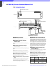
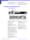
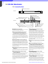
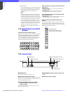
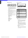
k IC card insertion block
A IC card slot
Insert an IC card (which conforms to PCMCIA)
to store reference files and scene files of the
video camera or CCU (SRAM CARD ONLY).
To insert a card
[1] Slide the cover to open the IC card insertion
block.
[2] Insert the card into the slot. When the card
is correctly set, the ACCESS indicator lights
in green.
Note
The data in the memory card is maintained by
the battery built into the card. If the battery is
exhausted, the data in the card will be lost. You
can check the battery condition by the ACCESS
indicator. If the battery becomes weak, replace
the battery with a new one as soon as possible.
B Eject button
Press to eject the inserted IC card.
Note
Do not eject a card when the ACCESS indicator
is lit in red (it means that the data is being read
from or written to the card). This may erase data
stored in the card.
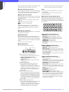
C ACCESS indicator
Shows the status of the IC memory card.
For battery replacement, refer to the instructions for the IC
card.
12345
STORE
SCENE FILES
1
2
MODE
MULTI
CARD
CONFIG
MAINTENANCE
FILE
PAINT
1
3
2
Indication Meaning or Measures
Off No card is inserted.
Lit in
green
There is a card in the slot. (The battery
condition is good.)
Lit in
orange
The battery of the card in the slot begins
losing its charge. Although the data are
still maintained, replace the battery at the
earliest opportunity..
Flashes in
orange
The battery of the card in the slot is
almost exhausted. While the card stays
in the MSU-700A, the MSU-700A sup-
plies the power to the card. However
when the card is ejected, the data can-
not be maintained. Replace the battery
before using.
Lit in red
Data are being read/written. If you eject
the disc in this condition, the data is not
guaranteed. All the data may be lost
ACCESS
1
3
2