


7
Chapter 7 Location and Function of Parts and Controls 94HDC-900/950/930 Series Product Information Manual
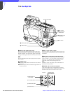
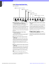
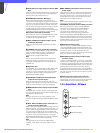
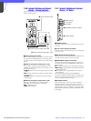
7-3-10 Internal Boards – AT board
a INCOM SELECT (intercom select) switch
Selects the intercom line to which the intercom signal
to be connected via the intercom connector of this unit.
PROD: producer line
PRIVATE: private line
ENG: engineer line
b PGM MIX (program mix) control
Controls the volume of program audio to be mixed to
the intercom signal at the headset.
c SIDE TONE control
Controls the volume of your voice to be supplied to the
receiver of the headset.
d TALK LEVEL control
Controls the volume of your voice to be sent to the
producer line, engineer line, and headset of the
camera.
e MIC LEVEL CH1/CH2 (CH1/CH2 microphone
level) controls
Control the input level according to the sensitivity of the
microphone connected to the MIC connector of the
camera so that an appropriate sound volume is
obtained.
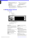
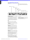
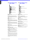
7-4. HDCU-950, HD Camera Control Unit
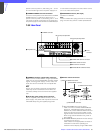
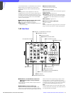
7-4-1 Front Panel
a Tally lamp
The lamp lights in red when a red tally signal is
received. When the CALL button on the camera, MSU-
700A/750 Master Setup Unit, RCP-700-series Remote
Control Panel, etc. is pressed, this lamp will go dark if
previously lit, and light up if previously off. It lights in
green when a green tally signal is received. A supplied
number plate can be mounted here.
b CABLE ALARM indicators
OPEN (red): The LED lights when there is no camera
connected via an optical fiber cable to the CAMERA
connector on the rear panel. It flashes to warn about
insufficient optical reception status of the optical
fiber cable.
SHORT (red): The LED lights when there is a short
circuit between a power supply line and the sheath
of the optical fiber cable, or when the two power
supply lines are shorted. When this indicator lights,
the power supply to the camera is shut off.
c POWER switch and indicators
The switch turns on or off the power to the entire
system, consisting of the HDCU-950, a video camera,
an RCP-700-series Remote Control Panel connected
via the REMOTE connector, etc. The MAIN and CAM
(camera) indicators light when the power is turned on.
POWER
REFERENCE H PHASE
MIC LEVEL
2 WIRE
CANCEL
TALK
LEVEL
CCU
/1.001
REF
IN
GEN
LOCK
PGM
MIX
SIDE
TONE
PROD ENG
INCOM
SELECT
NORM
CH-1
FINE
MIN
NORM
CH-2
MIN
LOCAL REMOTE
BBHD
PRIVATE
ENG PROD
AT
1 INCOM SELECT switch
2 PGM MIX control
3 SIDE TONE control
4 TALK LEVEL control
5 MIC LEVEL CH1/CH2 controls
HD CAMERA CONTROL UNIT
PROD
SHORT
OPEN
CAM
MAIN
CABLE
ALARM
INCOM
POWER
1
ENGPGM
ONMIC
OFF PRIV
1 Tally lamp
2 CABLE ALARM indicators
3 POWER switch and indicators
4 MIC/PGM switch
5 Intercom volume control
6 Intercom line selector
7 Intercom connector