


7
Chapter 7 Location and Function of Parts and Controls 78HDC-900/950/930 Series Product Information Manual
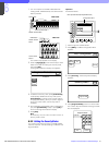
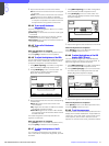
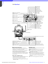
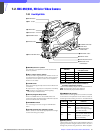
f Cable clamp
Used to secure the fiber optic cable. The clamp is
designed for the FC2-PD50 and FC2-PD250.
g Accessory bracket
Used to secure optional accessories such as the BKP-
7911/7912 Script Holder or Focus/Zoom Demand.
For more information on attaching an accessory, see the
accessory’s operation manual.
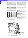
h AUDIO IN CH-1 and CH-2 connectors (XLR 3-pin)
Used to input microphone or line signals.
i AUDIO IN switch
Set this switch according to the device connected to
the AUDIO IN CH-1 and CH-2 connectors.
MIC: When connecting microphones
LINE: When connecting line signal sources
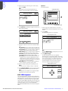
j Microphone power switches
For the microphones connected to the AUDIO IN CH-
1 and CH-2 connectors, respectively.
+48 V: When the connected microphone requires an
external power source. A power of +48 V is supplied
to the microphone.
OFF: When the connected microphone requires no
external power.
Note
To supply a power of +12 V, modification of the camera
is required. For details, refer to the Installation &
Maintenance Manual. Note that the modification must
be performed by service personnel.
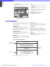
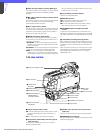
k PROMPTER connector (BNC type)
Used to output the signal input from the HDCU-900
Camera Control Unit’s PROMPTER INPUT connector.
l TEST OUT (test signal output) connector (BNC
type)
Used to output the signal selected by the video signal
select buttons on the rear panel. If the RET 1 or RET 2
button is pushed in, the output will be a return video
signal.
m REMOTE connector (8-pin)
Used to connect the camera to an optional MSU-700A/
750 Master Setup Unit or RCP-700 series Remote
Control Panel, via a CCA cable. The connected unit
may then control the HDC-900.
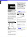
n TRACKER connector (20-pin)
Used for communication between the camera operator
and the tracker, and also for intercom channels 1 and
2. It also supplies the up tally signal and the program
audio signal.
o RET (return video) CONTROL connector (6-pin)
This connector allows an external controller to switch
return video 1, 2, and 3, as well as turn the intercom
microphone on and off.
p DC OUT connector (4-pin)
Used to supply power (12 V, 5 W maximum) to a script
light of the BKP-7911/7912 Script Holder.
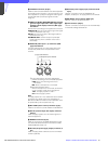
q CCU (camera control unit) connector (electro
optical multi-connector)
Connect to the CAMERA connector of the HDCU-900
Camera Control Unit using an electro-optical
composite cable. Power and video, audio, and control
signals are passed between the camera and the
control unit using just one cable.
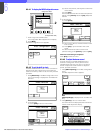
r DC IN connector (4-pin)
Connect to a DC power source (10.5 to 17 V) when
using the HDC-900 as a stand-alone unit.
s AC OUT connector
Used to supply AC power (200 VA maximum).
t VTR connector (26-pin)
When using the camera in stand-alone use, a VTR can
be connected using an HDCZ cable to this connector.
In this case, however, the VTR cannot be started or
stopped from the camera.
u HD SERIAL OUT connector
A serial digital interface with a transfer speed of 1.5
Gbps, this connector may be used to output a video
signal to a monitor or VTR.