


7
Chapter 7 Location and Function of Parts and Controls 137HDC-900/950/930 Series Product Information Manual
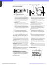
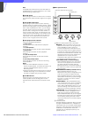
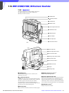
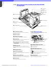
a PEAKING control
*1
When the PEAKING switch b is set to ON, this control
can be used to sharpen the edges in the picture.
Turning the control clockwise will increase the
sharpness. The peaking can be adjusted from 0 to 18
dB.
b PEAKING switch
When this switch is set to ON, peaking can be adjusted
using the PEAKING control a. When the switch is set
to OFF, the PEAKING control a is disabled, and the
peaking value will be 0 dB.
c Friction adjustment knob
Used to adjust the amount of friction in the tilting
mechanism.
d Lift-lock release knob
The viewfinder height can be adjusted while pulling
this knob. By releasing the knob after adjusting the
height to the standard (low), middle position, or top
position, the viewfinder will remain fixed at that height.
e POWER switch
Turns the power supply from the camera to the
viewfinder on and off.
f (attention) indicator
This indicator lights when the camera detects certain
conditions. The particular conditions which cause the
indicator to light up are set by the camera.
For information on how to set up and verify the
conditions under which the ! indicator will light, refer to
the manual for the camera being used.
g Green tally lamps
*2
Light up when the camera receives a green tally signal.
h BRIGHT (brightness) control
*1
Used to adjust the picture brightness.
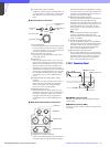
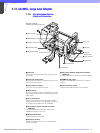
i Lock lever
This lever is used to lock the viewfinder into a desired
angle. The angle is locked when the lever is pushed
toward the camera lens. When the lever is pulled
toward the back of the camera, the angle can be
adjusted. The tilt mechanism will resist movement with
the amount of friction set by the friction adjustment
knob c.
j CONTRAST control
*1
Used to adjust the picture contrast.
k TALLY ON/OFF switch
Controls the external tally lamp n. When set to ON, the
external tally lamp will operate. When set to OFF, the
lamp will not operate (will not light in response to a tally
signal).
l BATT (battery) indicator
This indicator blinks when the voltage output of the
camera battery drops. When the battery reaches a
point that it may no longer be used, the indicator will
light up. To prevent camera shutdown due to the
battery running down, change the battery as soon as
possible after this indicator begins blinking.
The threshold battery voltage value to make this
indicator begin blinking is set by the camera. For
details, refer to the manual for the camera.
m Red tally lamps
*2
Light up when the camera receives a red tally signal.
n External tally lamp
Lights up red in response to a red tally signal. Can be
used to display the camera number by attaching one
of the supplied number plates (0 through 9).
o External tally dimmer control
Used to adjust the brightness of the external tally lamp.
Use a screwdriver to turn the control clockwise to
increase the brightness, or counterclockwise to dim
the lamp.
p CAMERA connector (D-sub 25-pin)
Used to connect to the camera’s viewfinder connector.
q Mounting wedge
To attach the viewfinder to a camera, the mounting
wedge is inserted into the V-shaped groove on the top
of the camera.
*1 These controls have no effect on the camera’s video output
signals.
*2 The brightness of these lamps can be adjusted using
controls inside the viewfinder body.