


7
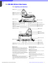
Chapter 7 Location and Function of Parts and Controls 81HDC-900/950/930 Series Product Information Manual
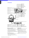
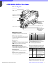
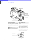
s Back tally lamp
This lamp lights red when the red tally signal is
supplied. When the CALL button on the MSU-700A/
750 Master Setup Unit or the RCP-700 series Remote
Control Panel is pressed, the lamp lights if previously
off or goes off if previously on. The brightness of the
lamp may be adjusted using a control provided in the
camera.
Attach a supplied number plate (0 through 9) to
display the camera number. Lights green when the
green tally signal is supplied.
t Memory Stick media card section
Insert a Memory Stick media card into the slot. The
lamp lights while writing or reading data to/from a
Memory Stick media card.
u RETURN SELECT knob 1
This knob selects from the four return signals from the
CCU. By pressing in the RET 1 button, you can view
the selected return video signal in the viewfinder.
v RETURN SELECT knob 2
This knob selects from the four return signals from the
CCU. By pressing in the RET 2 button, you can view
the selected return video signal in the viewfinder.
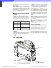
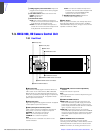
w RET 1 button
By pressing in this button, you can view the return
video signal selected by the RETURN SELECT knob 1,
in the viewfinder. Pressing this button again will switch
the viewfinder screen display and MONITOR output
back to the camera’s video signal.
x RET 2 button
By pressing in this button, you can view the return
video signal selected by the RETURN SELECT knob 2,
in the viewfinder. Pressing this button again will switch
the viewfinder screen display and MONITOR output
back to the camera’s video signal.
Note
If both the RET 1 and RET 2 buttons are pressed, RET
1 will be displayed.
y CURSOR STORE button
Press this button to store the size and position of the
box cursor in memory.
Note
If the CURSOR ON button is not lit, box cursor
information will not be stored.
z CURSOR ON button
When this button is pressed, the button will light up and
the box cursor will be displayed on the viewfinder
screen. When the button is pressed again, the light will
go off and the box cursor will disappear.
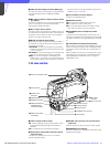
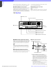
wj HEIGHT control
Adjust the height of the box cursor displayed on the
viewfinder screen within the effective resolution area.
wk V-POSI (vertical position) control
Adjust the vertical position of the box cursor displayed
on the viewfinder screen within the effective resolution
area.
wl WIDTH control
Adjust the width of the box cursor displayed on the
viewfinder screen within the effective resolution area.
e; H-POSI (horizontal position) control
Adjust the horizontal position of the box cursor
displayed on the viewfinder screen within the effective
resolution area
ea VF (viewfinder) connector (D-sub 25-pin)
Connect to the viewfinder CAMERA connector.
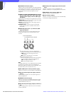
es INTERCOM 1 and 2 connectors (XLR 5-pin)
• Connects to an XLR 5-pin headset. The INTERCOM
1 connector may be used for communications even
when the power to the camera is turned off by the
HDCU-900 Camera Control Unit. Installing the BKP-
7913 RTS Intercom System Kit (option) allows the
INTERCOM 2 connector to work with an RTS
intercom system, and be connected to up to two
channel devices.
• These connectors may also be used for monitoring a
VTR playback audio signal when the HDC-900 is
used as a stand-alone unit.
ed INTERCOM PROD/ENG (intercom producer/
engineer line select) switch
Used to switch intercom channel 1 or 2 between
producer and engineer lines.
PROD: Use the producer line.
ENG: Use the engineer line.
ef INTERCOM volume control
Adjust the intercom output level.
eg PGM 1/2 (program audio select) switch
Used to switch between program audio 1 and 2.
eh PGM (program) volume control
Adjust the program audio output level.
ej MIC (microphone) ON/OFF switch
Turn the headset microphone on or off.