


7
Chapter 7 Location and Function of Parts and Controls 93HDC-900/950/930 Series Product Information Manual
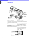
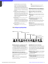
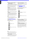
c FRAME REFERECE IN/OUT connectors (BNC
type)
The IN connector is used to receive an HD tri-level
reference sync signal or SD reference sync signal
(black burst signal) for frame sequence lock between
camera control units. In this case, the signal supplied
to the IN signal is output from the OUT connector as-is.
When this unit is used as the master unit, these
connectors can be used as the frame sync pulse
output connectors for pull down. Switching is made
using the switches on the internal FC board.
d SERIAL OUTPUT 1 to 3 and MONI (monitor)
connectors (BNC type)
The 1 to 3 connectors output the signal from the
camera as three HD-SDI signals. The MONI connector
outputs the signal from the video camera mixed with
skin tone gate signals and some aspect marker signal
in HD-SDI format.
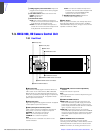
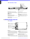
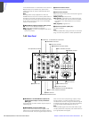
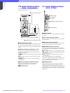
7-3-8 HKCU-904 Line Converter Unit
The optional HKCU-904 is to be installed in the HDCU-
900 expansion slot or in place of the SD signal input/
output block.
Note
When used in combination with the HKCU-903, mount
the HKCU-903 into the second slot from the top, and
the HKCU-904 into the third slot.
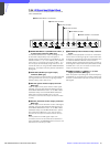
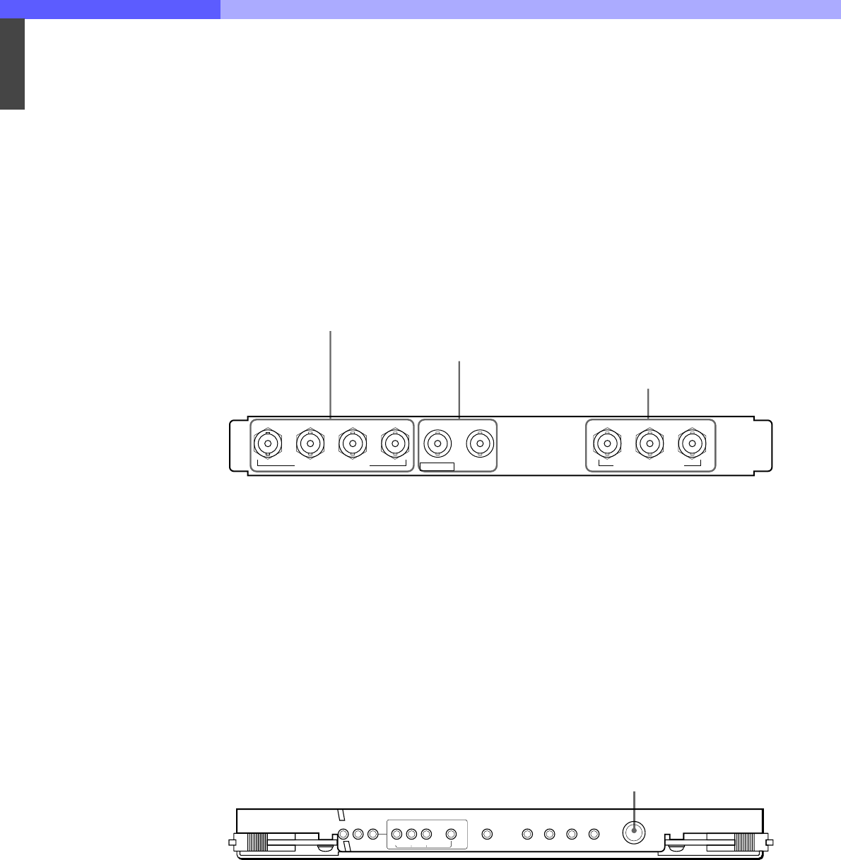
a SERIAL RET INPUT 1-4 (HD-SDI return video 1,
2, 3, and 4 input) connectors (BNC type)
Four different HD-SDI analog return video input signals
(720/60P) may be received independently. The
selection of RET 1, 2, 3, or 4 is made by the camera’s
return switch. The type of input signal on RET 1, 2, 3,
and 4 may be set individually using switches on the AT
board in the HDCU-900, or using the MSU-700A/
750 Master Setup Unit.
b SYNC OUT (HD/SD sync signal output)
connectors (BNC type)
The left connector outputs a sync signal of the same
format as that of the input/output block in the above
slot. The right connector outputs the HD tri-level sync
signal of the same format as that of the SERIAL
OUTPUT 1 to 3 connectors.
c SERIAL OUTPUT 1 to 3 connectors (BNC type)
The 1 to 3 connectors output the signal from the
camera as three HD-SDI signals (720/60P).
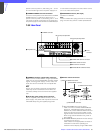
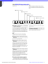
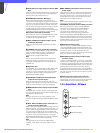
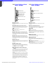
7-3-9 Internal Boards – DPR board
AUDIO PHASE control
Adjusts the delay of the audio signal with respect to the
video signal output from this unit. (1 step=5 ms, 1-
frame delay: 30 frames/s=7, 25 frames/s=8)
1234 123
SERIAL RET INPUT
SYNC OUTSYNC OUT
SERIAL OUTPUT
1 SERIAL RET INPUT 1-4 connectors
2 SYNC OUT connectors
3 SERIAL OUTPUT 1 to 3 connectors
DPR
POWER /1.001
60
MAIN OUTPUT
AUDIO PHASE
50 PsF
CHU LOCK
540P 1035
OPTICAL
CONDITION
30 25 24
CCU CHU
SYSTEM
POWER
AUDIO PHASE control