


7
Chapter 7 Location and Function of Parts and Controls 105HDC-900/950/930 Series Product Information Manual
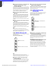
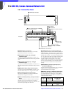
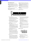
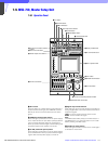
7-7. VCS-700, Video Selector
7-7-1 Front and Rear Panels
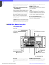
a POWER switch and indicator
This switch turns the power ON and OFF. The indicator
illuminates when power is switched on.
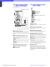
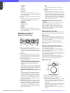
b PIX1 through PIX6 INPUT (picture monitor 1
through 6 inputs) connectors (BNC type)
Accept video signals for a picture monitor. Connect
each of these connectors to the PIX2 OUTPUT
connector on the CCU-700A/700AP Camera Control
Unit. The signal loss of a connecting cable up to about
30 meters (99 feet) long can be compensated for with
the switch on the internal board. For details, refer to the
system manual.
c CHARACTER INPUT connectors (BNC type)
Accept character signals. The input signal is mixed
with the signal output from the PIX OUTPUT connector.
Connect to the CHARACTER connector on the CNU-
700 Camera Command Network Unit. When using two
VCS-700 units, connect either of these connectors to
the CHARACTER INPUT connector on a second VCS-
700. When a bridge connection is not made, be sure to
terminate with 75 ohms.
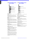
d PIX A INPUT (picture monitor A input) connector
(BNC type)
Connect to the PIX A OUTPUT connector on a second
VCS-700 when using two or more VCS-700 selectors.
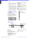
e PIX A OUTPUT (picture monitor A output)
connector (BNC type)
Supplies a video signal for a picture monitor. Select the
output signal with the camera select buttons on an
MSU-700 or by command from the I/O PORT
connector on the VCS-700 Video Selector. When using
two or more VCS-700 units, connect this connector to
the PIX A INPUT connector on each subsequent VCS-
700, and a picture monitor to the PIX A OUTPUT
connector on the final VCS-700 in the series
connection.
f PIX B OUTPUT (picture monitor B output)
connector (BNC type)
Supplies the same video signal for a picture monitor as
the PIX A OUTPUT connector. The signal loss of a
connecting cable up to about 100 meters (330 feet)
long can be compensated for with the switch on the
internal board. When you connect a picture monitor
using a long connecting cable, connect it to this
connector. When using two or more VCS-700 units
connected in series, connect a picture monitor to the
PIX B OUTPUT loop connector on the VCS-700 whose
PIX A OUTPUT connector is not used for series
connection. For details on cable compensation, refer
to the system manual.
g SYNC OUT (sync signal output) connector (BNC
type)
Supplies the sync signal for a picture monitor.
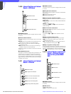
h WF1 through WF6 INPUT (waveform monitor 1
through 6 input) connectors (BNC type)
Accept video signals for a waveform monitor. Connect
these connectors as required to the WF2 OUTPUT
connector on CCU-700A/700AP Camera Control Units.
The signal loss of a connecting cable up to about 30
meters (99 feet) long can be compensated for with the
switch on the internal board. For details, refer to the
system manual.
i WF A INPUT (waveform monitor A input)
connector (BNC type)
Connect to the WF A OUTPUT connector on a second
VCS-700 when using two of these units.
j WF A OUTPUT (waveform monitor A output)
connector (BNC type)
Supplies the video signal for a waveform monitor.
Select the output signal with the camera select buttons
on an MSU-700 or by command from the I/O PORT
connector on a VCS-700. When using two or more
VCS-700 units, connect this connector to the WF A
INPUT connector on each subsequent VCS-700, and a
POWER
VIDEO SELECTOR
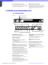
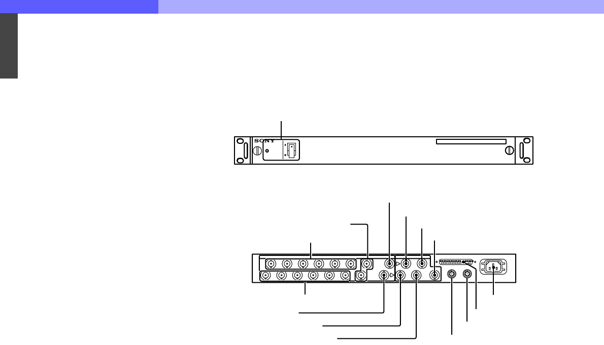
1 POWER switch and indicator
Front panel
3 CHARACTER INPUT connectors
8 WF 1 through WF 6 INPUT connectors
9 WF A INPUT connector
q; WF A OUTPUT connector
qa WF B OUTPUT connector
2 PIX 1 through PIX 6 INPUT connectors
4 PIX A INPUT connector
5 PIX A OUTPUT connector
6 PIX B OUTPUT connector
7 SYNC OUT connector
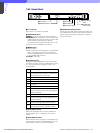
qg -AC IN connecto
r
qf I/O PORT connector
qd REMOTE connector
qs WF MODE connector
Rear Panel