


7
Chapter 7 Location and Function of Parts and Controls 103HDC-900/950/930 Series Product Information Manual
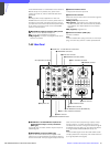
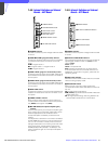
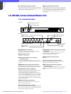
j ~AC IN (AC power input) connector
Connect to an AC power source using the supplied AC
power cord. The power cord can be fixed to the CNU-
700 using the supplied plug holder.
k Optional board insertion section
Used for attaching the connector panel of an optional
BKP-7930/7933. When you attach the BKP-7930 to the
CNU-700, up to 12 cameras and remote control panels
can be controlled. BKP-7933 enables the S-bus
functionality.
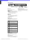
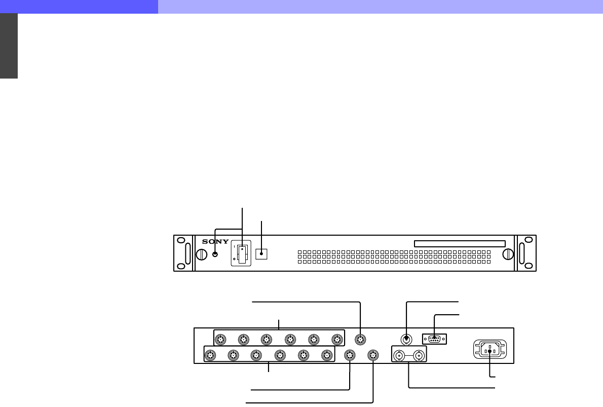
7-6. CNU-500, Camera Command Network Unit
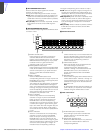
7-6-1 Front and Rear Panels
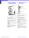
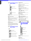
a POWER switch and indicator
Press to turn the power ON or OFF. The indicator
illuminates when power is switched on.
b CNU number indicator
Attach the number plate.
c CCU (camera control unit) 1 through 6
connectors (8-pin)
Connect to the RCP/CNU/ REMOTE connector of a
CCU-700A/700AP Camera Control Unit using a CCA-5
cable.
d MSU (Master Set-up Unit) connector (8-pin)
Connect to the CCU/CNU REMOTE connector on an
MSU-700 Master Set-up Unit using a CCA-5 cable.
e CHARACTER connector (BNC type)
Supplies character data as a 525 or 625-line, black-
and-white video signal. The signal output is
automatically selected according to the reference
signal input to the REFERENCE connector. If no signal
is input to the REFERENCE connector, the CNU-500
for the USA and Canada supplies a 525-line video
signal, and the CNU-500 for other countries supplies a
625-line video signal.
f RS-232C connector (D-sub 9-pin)
Used for the RS-232C interface. This connector is
reserved for the ISR system.
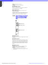
g ~AC IN (AC power input) connector
Connect to an AC power source using the supplied AC
power cord. The power cord can be fixed to the CNU-
500 using the supplied plug holder.
h REFERENCE (reference signal input) connector
(BNC type)
Accept a reference signal (VS, BS, etc.). The signal
output from the CHARACTER connector is
synchronized with the input signal.
i AUX (auxiliary) connector (8-pin)
Not used.
j VCS (video selector) connector (8-pin)
Connect to the REMOTE connector of a VCS-700
Video Selector using a CCA-5 cable.
k RCP (remote control panel) 1through 6
connectors (8-pin)
Connect to the CNU/CCU REMOTE connector on RCP-
700 Series Remote Control Panels using a CCA-5
cable.
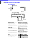
~AC IN
POWER
CCU1 CCU2 CCU3 CCU4 CCU5 CCU6
MSU
CHARACTER
RS232C
CAMERA COMMAND NETWORK UNIT
1 POWER switch and indicator
2 CNU number indicator
Front panel
Rear panel
qa RCP 1 through 6 connectors
q; VCS connector
9 AUX connctor
4 MSU connector
3 CCU 1 through 6 connectors
5 CHARACTER connector
6 RS-232C connector
7 -AC IN connector
8 REFERENCE
connectors