


7
Chapter 7 Location and Function of Parts and Controls 96HDC-900/950/930 Series Product Information Manual
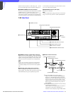
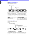
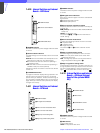
c SYNC OUT (sync signal output) connector (BNC
type)
Used for output of an SD composite sync signal or HD
tri-level sync from the internal sync signal generator.
(Factory setting: SD composite sync)
d PROMPTER connectors (BNC type)
Input a teleprompter signal to either of the two
connectors. The input signal is output from the other
connector as-is (loop-through output). If loop-through
output is not used, terminate the unused connector
with 75 ohms. If the signal used is a 1.0-Vp-p, 75-ohm
analog signal, it may be output from the video
camera’s PROMPTER OUT connector with a frequency
bandwidth of 8 MHz, regardless of signal format.
RET4 (return video input 4) connector
When required, either of the PROMPTER connectors
can be assigned for the fourth return video input
exclusively for analog VBS signals.
e MIC1 and MIC2 (microphone output 1 and 2)
connectors (XLR 3-pin)
Used to output microphone signals from the video
camera
f CAMERA connector (optical fiber connector)
Used to connect a video camera, using an optical fiber
cable. All video camera signals, including power
supply, control, video, and audio, are sent and
received over one optical fiber cable.
Note
Dust on the connection surface of the optical fiber
cable may result in transmission errors. When not
connected, always keep the end covered with the
supplied cap.
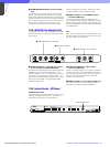
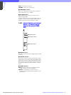
g Expansion slot
For installation of the optional HKCU-951 SD Encoder
Unit. When using the HKCU-953 HD Frame Rate
Converter Unit, move the DIF board and internal RC
board to this slot and install the HKCU-953 in the
original DIF/RC board position.
h INCOM/TALLY/PGM (intercom/tally/program
audio) connector (D-sub 25-pin)
Used for input and output of intercom, tally, and
program audio signals. Connect to the intercom/tally/
program audio connector of the intercom system.
i MONI (HD-SDI monitor output) connector (BNC
type)
The signal from the video camera can be mixed with
skin tone gate signals and some aspect marker signal
and output in HD-SDI format.
Note
Mixing is set to ON or OFF using switches on the
internal AT board or the MSU-700A/750 Master Setup
Unit.
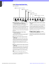
j RET1, RET2, and RET3 (return video input 1, 2,
and 3) connectors (BNC type)
Return video input signals can be received from three
different systems. The selection among from RET 1, 2
and 3 is made using the camera’s return video switch.
The type of input signal can be any of HD-SDI, SD-
component SDI, or analog VBS, and can be set using
the switch on the internal DTX board, or using the
MSU-700A/750 Master Setup Unit. Signals of different
types cannot be connected simultaneously.
Note
If a signal asynchronous with the HDCU-950 is
supplied, it may affect the picture quality of return
video.
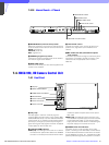
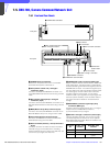
k MIC REMOTE (microphone remote) connector
(D-sub 15-pin)
Using this connector, the video camera’s microphone
amplifier gain can be set using external equipment
such as an audio mixer, in five steps (60, 50, 40, 30,
and 20 dB). When taping, set the volume to a level
appropriate for the audio conditions.
Note
The microphone amplifier gain can also be set using
switches on the internal AVP board.
WF REMOTE (waveform monitor remote) connector
With the internal switch setting, the MIC REMOTE
connector can be assigned for the WF REMOTE
connector. In this case, the connector can be
connected to the appropriate connector on a
waveform monitor when operating the waveform
monitor using an MSU-700A/750 Master Setup Unit or
RCP-700- series Remote Control Panel. A recall-type
monitor can be connected. For the recall-type monitor,
preset a display mode on the waveform monitor, and
then recall the mode externally.
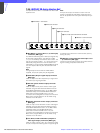
l RCP/CNU connector (8-pin)
Used to connect to an MSU-700A/750 Master Setup
Unit, CNU-500/700 Camera Command Network Unit,
or RCP-700-series Remote Control Panel via a CCA-5
Connection Cable. Control signals are sent and
received via this connector. When using an RCP-700-
series unit, power is also supplied.
m WF MODE (waveform monitor mode output)
connector (4-pin)
Connect to the appropriate connector on a waveform
monitor when monitoring a signal in Sequential mode.
A sequence signal will be output when the SEQ button
on the MSU-700A/750 Master Setup Unit or RCP-700
Series Remote Control Panel is pressed, allowing
simultaneous monitoring of the R, G, and B signals in
Sequential mode. (When both the RCP and MSU are in
use, this connector functions as the output connector
for RCP control.)
n AC IN (AC power supply input) connector
Use the specified power cord to connect to an AC
power supply. The power cord can be secured to the
HDCU-950 body using an optional plug holder.
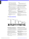
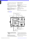
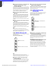
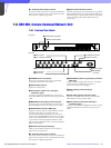
7-4-3 Output Block - DIF Board
RC
SD SDI
OUT 1
SD SDI
OUT 2
PIX
OUT
WF
OUT
1 SD SDI OUT 1 and SD SDI OUT 2
connectors
2 PIX OUT connector
3 WF OUT connector