


4
Chapter 4 Control System 60HDC-900/950/930 Series Product Information Manual
4-5. Auto Set-up
The HDC-900 and HDC-950/930 cameras incorporate
a sophisticated Auto Setup system to adjust the video
processing circuitry parameters for optimum color
matching. In addition to auto white balance, auto black
balance and auto level set-up, the following
parameters can also be adjusted according to a
reference file.
• Auto white shading (The shading compensation is
achieved with horizontal and vertical sawtooth and
parabolic waveform as well as with a digitally
synthesized waveform for almost 1000 individual
correction zones created by DSP.)
• Skin detail auto hue (automatic hue detection for
specified color range, with full skin detail function.)
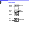
4-6. Control Priority and Parallel Mode
Control Priority
When a camera system is configured using the CNU-
700 or CNU-500, each camera can be connected in
parallel to both an RCP-700 Series Remote Control
Panel and the MSU-700A/750 Master Setup Unit, and
is controlled from whichever unit has control priority.
Priority for iris/master black adjustments only can be
obtained when the IRIS/MB ACTIVE button on the
panel on which the PANEL ACTIVE button is not lit.
When the MSU-700A/750 is in the panel active status,
only the iris and master black controls are inoperative
on the MSU-700A/750 and can be set by pressing the
lit IRIS/MB ACTIVE button.
Parallel Mode
The MSU-700A/750 and RCP-700 Series panels have
a PARA button to select Parallel Mode. When the PARA
button of the unit is pressed and lit, Parallel Mode is
activated and all the control functions, other than the
iris/master black controls, become operative from both
units. The Parallel Mode can be canceled by pressing
the PARA button of the MSU-700A/750 or RCP-700
Series control panel.
4-7. S-BUS Control
The S-Bus Concept
A further advantage of the Sony camera control system
is the 'S-Bus control' technique, which is based on an
original Sony concept. Studio installations and OB
units use digital routers as the nerve center for a
complete audio/video system. With Sony system
integration, all the equipment is connected to the Sony
digital router via a LAN, called the 'S-Bus'. With the S-
Bus system, control and tally signals are interlocked so
that they, along with video and audio signals, can be
simultaneously switched from a central terminal. Each
input/output source can be given a name, which can
then be displayed on the source name display panel of
a DVS-7000/8000 Series Video Switcher or on the BKS-
R3280/R3281 Status Character Display. One example
of the operational advantages of the S-Bus system is
that the routing of input signals to the primary inputs -
of a DVS-7000/8000 Series Video Switcher can be
changed at any time without having to re-connect
cables. Even the source name display, tally signal and
tally display are interlocked and changed
automatically.
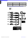
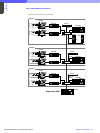
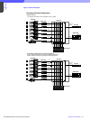
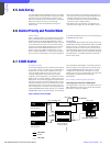
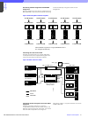
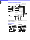
Sony camera command system with S-Bus
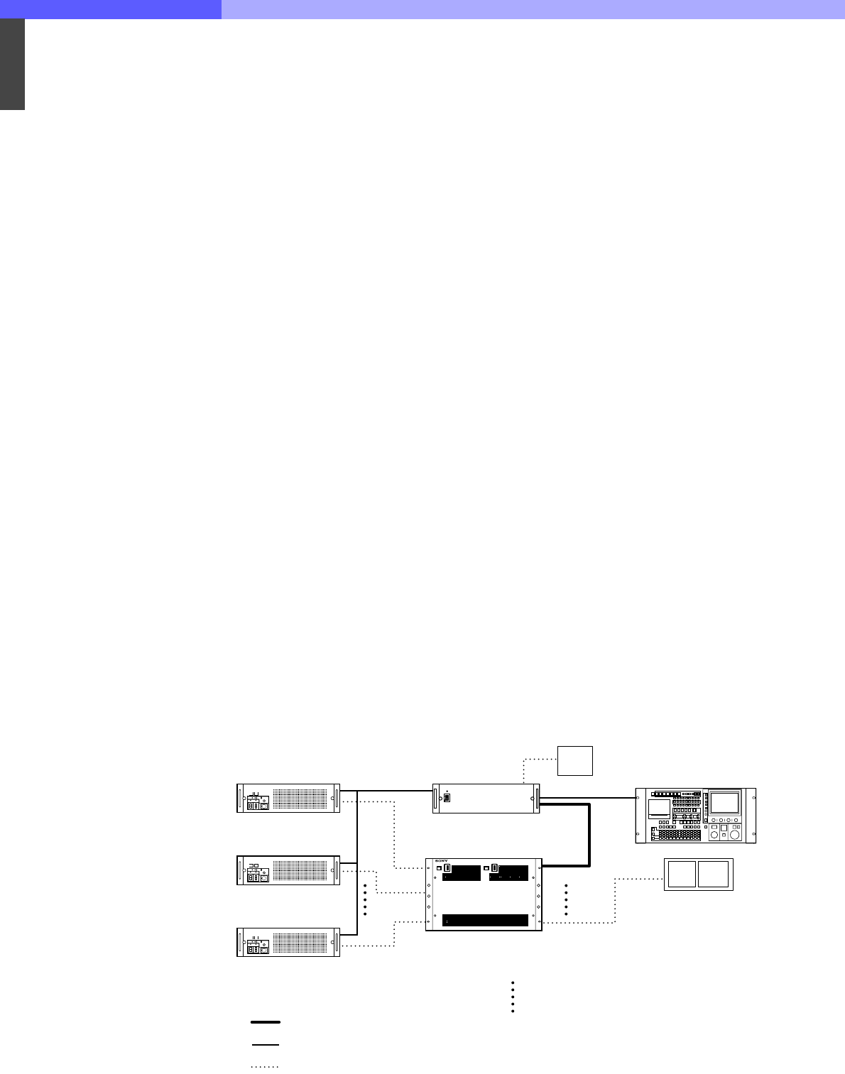
Controlling the router from an MSU panel
The digital router's cross point can switched from the
MSU-700A/750 by pressing its camera select button.
SDI video monitoring is enabled.
Figure 4-8: Router control from MSU
PIX
CNU character
HDCU-900
with A/D board
HDCU-900
with A/D board
HDCU-900
with A/D board
CNU with BKP-7933
PIX WFM
Router
(DVS-V3232 etc.)
Primary Station
SDI
IN1
IN2
IN5 OUT25
SDI Monitor
from MSU camera select
MSU-700A
S-BUS BNC
CCA-5
Video BNC
NTSC or PAL