


7
Chapter 7 Location and Function of Parts and Controls 132HDC-900/950/930 Series Product Information Manual
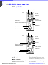
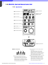
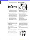
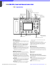
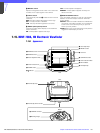
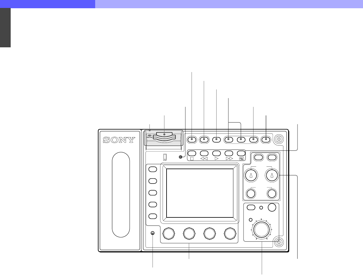
7-13. RM-B750, Hand-held Remote Control Unit
7-13-1 Operation Panel
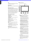
a Memory Stick slot
Insert a Memory Stick to store setting data, such as
reference files and scene files of the video camera or
camera control unit.
b MEMORY STICK (Memory Stick access) lamp
The lamp shows the status of the Memory Stick.
Off: No Memory Stick is inserted.
Lit in green: There is a Memory Stick in the slot. In this
condition, you can safely eject the Memory Stick.
Lit in red: Data are being read/written. If you eject the
Memory Stick in this condition, the data are not
guaranteed. All the data may be lost.
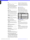
c PANEL ACTIVE button
Press to select the control mode for the connected
camera system. Each time you press the button with
the factory setting, the control mode cyclically
switches among FULL, PART, and LOCK modes.
FULL mode: All controls from this unit are enabled
(panel active status). Both this button and the IRIS/
MB ACTIVE indicator in the iris/master black control
block light.
PART mode: Controls only from the iris/master black
control block are enabled (iris/master black active
status). This button goes dark, but the IRIS/MB
ACTIVE indicator stays lit.
LOCK mode: All controls from this unit are disabled
(lock status). Both this button and the IRIS/MB
ACTIVE indicator in the iris/master black control
block go dark.
Using the RM Configuration menu under the
Maintenance menu, the function of this button can be
changed to switch only between FULL and LOCK
modes. The RM Configuration menu operation is
possible in any mode.
d STANDARD button
When you press this button, the video camera is
initialized to its standard state, and the button lights for
several seconds. If you press the button while lit, the
video camera retrieves the state before the button was
lit.
e Spare button
For future use.
f Test signal output select buttons
Press and light up one of these buttons to activate the
test signal generator of the video camera and send the
respective signals.
TEST: To send a signal to test the video circuits. You
can select the kind of the test signal to be output
using the RM Configuration menu under the
Maintenance menu.
BARS: To send a color bar signal
6 Test signal output select buttons
7 CLOSE button
8 VTR START/STOP button
9 VTR playback
control buttons
MONITOR
FUNCTION
VF DISP
MENU SELECT
MAINTENANCE
VF MENU
SCENE
CANCEL
PAINT
ENTER
ALARM
PANEL
ACTIVE
MEMORY
STICK
STANDARD TEST BARS CLOSE
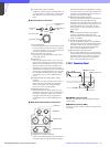
AWB
AUTO
IRIS
IRIS/MB
ACTIVE
MASTER
BLACK
REMOTE CONTROL UNIT RM-B750
EXT
IRIS
WHITE
BLACK
ABB
VTR
START/STOP
qd White balance/black
balance control block
q; ALARM indicator
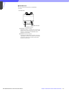
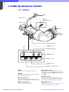
Rubber cap
2 MEMORY STICK lamp
3 PANEL ACTIVE button
4 STANDARD button
5 Spare button
qs Iris/master black control block
qa Menu operation block
1 Memory Stick slot