


7
Chapter 7 Location and Function of Parts and Controls 104HDC-900/950/930 Series Product Information Manual
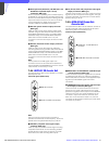
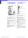
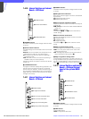
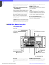
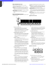
7-6-2 Internal Board
a +5 V indicator
Lights when +5 V power to the board.
b OPERATION switch
NORMAL: Set to this position for normal operation.
EMERGENCY: Set to this position when the CNU-500
or MSU-700 cannot function normally. The RCP-700
Series Remote Control Panels are directly
connected to their respective camera control units.
The switch is set to NORMAL at the factory.
c MODE switch
0: Factory setting
1: When the switch is set to this position, the UP/DOWN
switch is activated, and the switch changes the
character page displayed on a monitor connected
to the CHARACTER connector.
2 through F: Not used.
d UP/DOWN switch
Changes the page displayed on the monitor screen.
This switch functions only when the MODE switch is set
to 1. The contents of each page are shown in the
following table.
e SET/CANCEL switch
Selects the displayed item or camera (CAM) when
display page 9, 10 or 11 appears on the monitor
screen.
f SYNC ON/OFF switch
Selects whether the sync signal is to be added to the
video signal output from the CHARACTER connector.
At the factory, the switch is set to ON (added).
g CHARACTER PHASE control
Adjusts the horizontal phase of the signal output from
the CHARACTER connector, referring to the reference
signal. Adjust the phase by monitoring the signal on
the monitor screen.
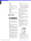
SYNC
CHARACTER
UP DOWN SET CANCEL
MODE
PHUSE OFF ON
OPERATION
NORMAL EMERGENCY
+5
3 MODE switch
4 UP/DOWN switch
5 SET/CANCEL switch
6 SYNC ON/OFF
switch
7 CHARACTER
PHASE control
1 +5 V indicator
2 OPERATION switch
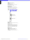
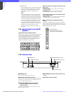
Page Contents
1
Nothing appears when power is turned on.
Shows a warning if a problem is detected by
the self-diagnosis of the camera.
2 Connection status of Cameras 1 through 6.
3 Not used.
4 Not used.
5
Shows the results of auto set-up of Camera 1
through 6.
6 Cannot be used.
7
DIAGNOSIS OF ALL CAMERAS displays,
which shows the results of the self-diagnosis
of all the cameras.
8 Not used.
9
DIAGNOSIS OF ONE CAMERA display, which
shows the results of the self-diagnosis of the
selected camera.
10
DATA OF ALL CAMERAS display, which
shows the setting status of each camera.
11
DATA OF ONE CAMERA display, which shows
the setting status of the selected camera.