


6
Chapter 6 A Quick Lesson on Camera Settings 68HDC-900/950/930 Series Product Information Manual
box. For this adjustment, a White Chart
exposed to a uniform light is also needed.
[2] Black shading - Execute AUTO BLK
SHADING for the models that have this
function. For manual adjustment, adjust in
12 (3 x 2 x 2) different combinations: R/G/B
channels (3), vertical (V) and horizontal (H)
(2) for each of them, SAW wave, and PARA
wave (2).
[3] White shading - Select a lens file. V-SAW in
white shading changes according to the
exit pupil of the lens. The exit pupil also
changes according to the zoom position
when using a zoom lens. The change
caused by the exit pupil appears on the G-
channel. For that, a MOD V SAW
adjustment should be carried out.
Sometimes the color matching between the
cameras may still not be in line even after a
gray scale adjustment. In most cases, this
is because the white shading is out of line.
6. Color matching between the cameras
Even after making the above camera adjustments
(Steps 5-(1) to 5-(9)), there still might be a very small
difference between the cameras. This difference is so
slight that it can usually be ignored. However, if it is
desired to make a closer match, then please proceed
as follows: Choose a camera as a standard reference
and adjust the levels of black, gamma and flare detail
of the other cameras to match those of the camera
chosen as the reference standard.
Notes
Be sure to situate each camera as close as possible to
each other because the reflected light changes
depending on the angle of reflection even when
shooting the same chart. There are always some
variances between different-model lenses. Fine
adjustment is needed even between the same model
lenses because the correction value cannot be the
same.
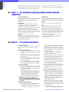
6-3. Initial Settings for the Control System
For a system using the MSU-700A/750, you need to set
parameters for control of your system from the MSU-
700A/750 as well as the operating conditions of the
MSU-700A/750. The MSU-700A/750 has an Engineer
Mode, which allows you to assign cameras to be
controlled from the MSU-700A/750 and to limit the
operations on the MSU-700A/750. To authorize
specific persons to use this Engineer Mode, specify a
security code in advance. Once the security code is
set, the MSU-700A/750 will enter into the Engineer
Mode when this security code is input.
6-3-1 Specifying the Security Code
You can set, change, or delete the security code for
entering into the Engineer Mode as follows:
6-3-1-1 To set a new security code
Note
At the factory the unit is set in a mode in which no
security code is used. To use a security code, it is
necessary to enable the use of a security code. See
"To enable to cancel the security code"
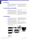
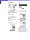
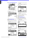
1. Press and light the CONFIG button.
The configuration menu appears on the display.
2. Press [MSU].
The MSU Configuration Menu appears.
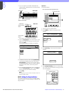
3. Press [Security].
The Security Menu display appears.
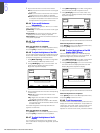
4. Press [Engineer Mode] to set it to inverse video.
The Security Menu items now appear.
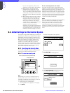
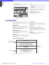
MODE
MULTI
CARD
CONFIG
MAINTENANCE
FILE
PAINT
Configuration Menu
2
1
MSUCNU
Camera
CCU
Menu operation block (Example:MSU-700A)
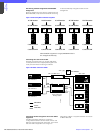
Configuration Menu
Security
MSU Configuration
MSU
Adjusting
Exit
Date /
Time
MSU SW
Set
Security Menu
Engineer Mode
Exit
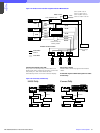
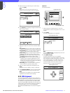
Security Menu
Status
Engineer Mode
Code
Change
Engineer Mode
Exit