


8
Chapter 8 Connectors and Cables 156HDC-900/950/930 Series Product Information Manual
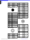
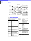
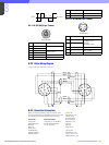
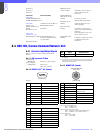
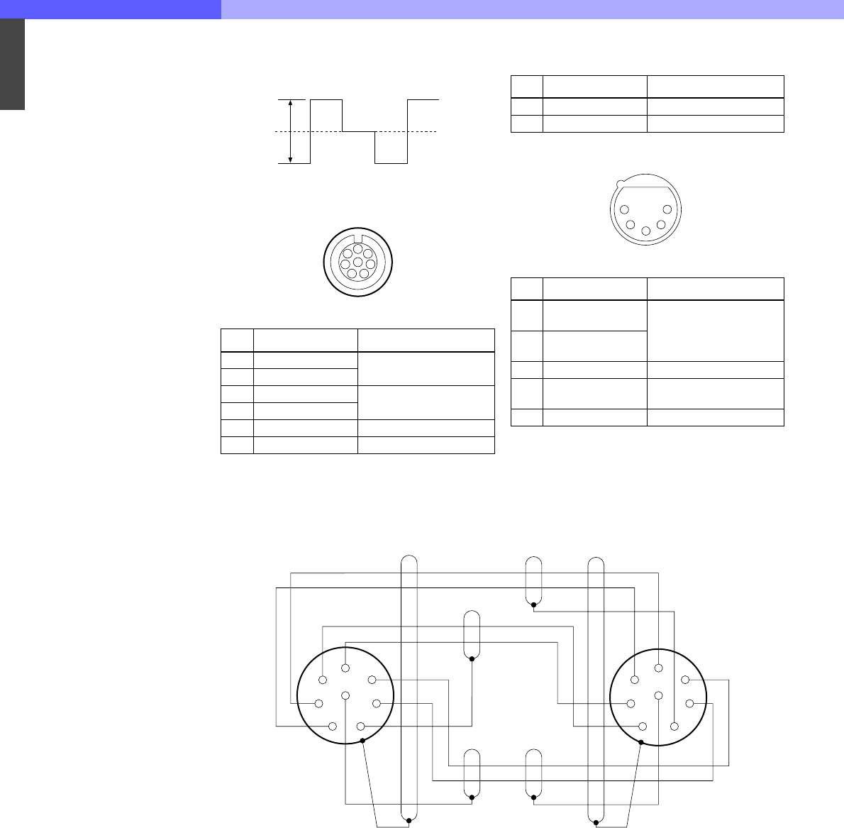
8-2-1-10 RCP/CNU (8-pin, Female)
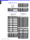
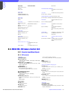
8-2-1-11 INTERCOM (5-pin, Female)
(0 dBu = 0.775 Vrms)
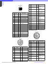
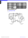
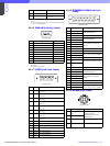
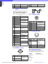
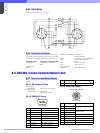
8-2-2 Cable Wiring Diagram
CCA-5 cable (for RCP/CNU connector)
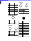
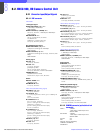
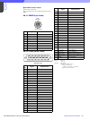
8-2-3 Connection Connectors
When connecting cables to each connector of the
connector panel during installation or service, connect
the following connectors or equivalent to the tip.
Connector Connector/cable
HDCU-900 1-564-742-11 PLUG, BNC
REFERENCE IN or B-B cable assembly
PIX OUT (1.5 m, optional)
WF OUT
SYNC OUT
CHARACTER
DIGITAL AUDIO
PROMPTER IN
HKCU-901
RET INPUT (1-4)
Y/G OUTPUT
B-Y/B OUTPUT
R-Y/R OUTPUT
VBS OUT (1-2)
PIX OUT
WF OUT
SYNC OUT
HKCU-902
RET INPUT (1-4)
Y/G OUTPUT (1-2)
PB/B OUTPUT (1-2)
No. Signal Specifications
1 TX (+) CCU SERIAL DATA
2TX (–)
3 RX (+) RCP/CNU/BVP/MSU/VCS
SERIAL DATA
4RX (–)
5 TX GND GND for TX
6 POWER (+) OUT RCP POWER, +30 V
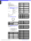
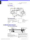
12
V
+1
- 6
RGB
DC 0 ±2 V
1
2
3
4
5
6
7
8
(External view)
7 POWER (–) OUT GND for POWER
8SPARE
No. Signal Specifications
1 INCOM (T) IN (Y) –20 dBu
(CARBON MIC)
–60 dBu
(DYNAMIC MIC)
2 INCOM (T) IN (X)
3 INCOM (T) IN (G) GND for INCOM
4 INCOM (R) OUT
(X)
GND for POWER
Max. 12 dBu
5 NC No connection
No. Signal Specifications
1
2
3
4
5
(External view)
Black
White
White
Brown
White
Red
Red
Brown Brown
Orange
1
2
3
4
8
5
6
7
1
2
3
4
8
5
6
7