


11/14/2008 RFID Programming Guide 58978L-008 Rev. A
10
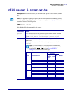
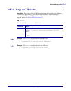
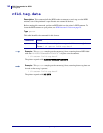
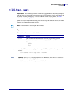
RFID Applicator Signals
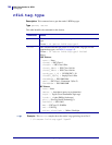
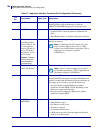
This section applies to printers that have applicator ports and that are being used in a print and
apply system. Included are timing diagrams for good and bad RFID tags and the pin
configuration for the applicator port. For basic timing diagrams, see the User Guide for your
printer.
Contents
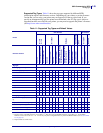
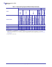
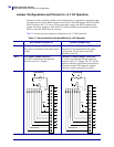
Timing Diagrams for RFID . . . . . . . . . . . . . . . . . . . . . . . . . . . . . . . . . . . . . . . . . . . . . . . 150
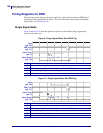
Single Signal Mode . . . . . . . . . . . . . . . . . . . . . . . . . . . . . . . . . . . . . . . . . . . . . . . . . . 150
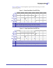
Double Signal Mode. . . . . . . . . . . . . . . . . . . . . . . . . . . . . . . . . . . . . . . . . . . . . . . . . . 152
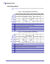
Applicator Interface Connector Pin Configuration . . . . . . . . . . . . . . . . . . . . . . . . . . . . . 153
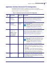
Jumper Configurations and Pinouts for +5 V I/O Operation. . . . . . . . . . . . . . . . . . . . 156
Pinouts for +24-28 V I/O Operation . . . . . . . . . . . . . . . . . . . . . . . . . . . . . . . . . . . . . . 157