


155
RFID Applicator Signals
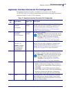
Applicator Interface Connector Pin Configuration
11/14/2008 RFID Programming Guide 58978L-008 Rev. A
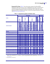
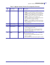
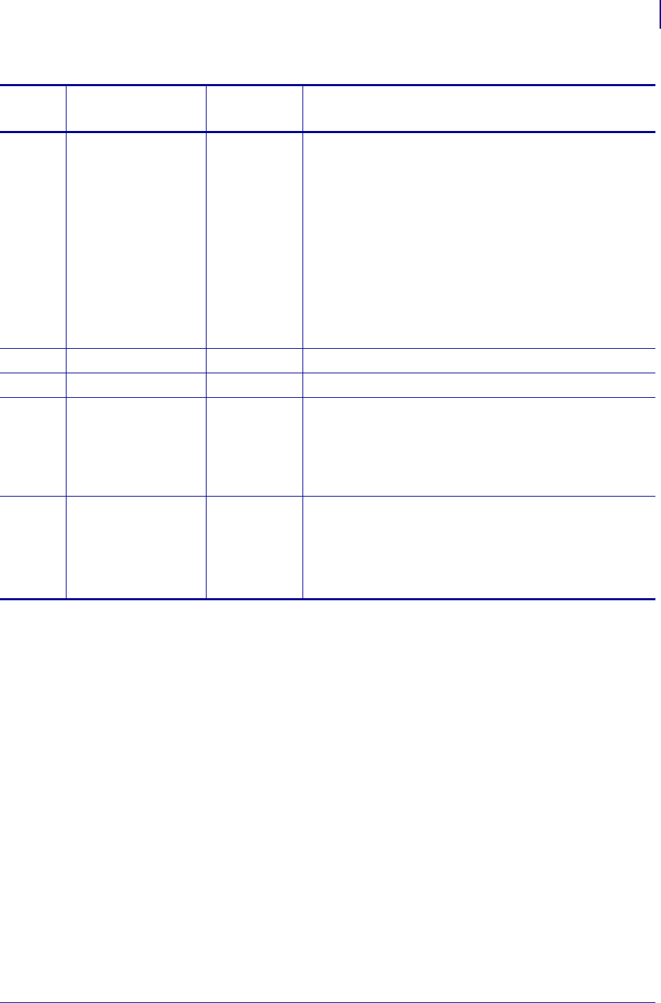
11 END PRINT Output • MODE 0—The applicator port is OFF.
• MODE 1—Asserted LOW only while the printer is
moving the label forward; otherwise deasserted HIGH.
• MODE 2—Asserted HIGH only while the printer is
moving the label forward; otherwise deasserted LOW.
• MODE 3—(Default) Asserted LOW for 20
milliseconds when a label is completed and positioned.
Not asserted during continuous printing.
• MODE 4—Asserted HIGH for 20 milliseconds when a
label is completed and positioned. Not asserted during
continuous printing.
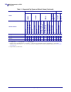
12 MEDIA OUT Output Asserted LOW while there is no media in the printer.
13 RIBBON OUT Output Asserted LOW while there is no ribbon in the printer.
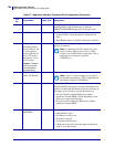
14 DATA READY Output • Asserted LOW when sufficient data has been received
to begin printing the next label.
• Deasserted HIGH whenever printing stops after the
current label, due to either a pause condition or the
absence of a label format.
15 VOID Output See Timing Diagrams for RFID on page 150 for more
information about this signal.
• Asserted LOW when the RFID transponder over the
antenna is “voided.”
• Deasserted HIGH when the end print signal is asserted.
Table 12 • Applicator Interface Connector Pin Configuration (Continued)
Pin
No.
Signal Name Signal Type Description