


Page setup
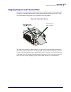
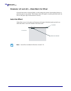
Aligning Preprint and Thermal Print
102
P1002902-002 TTP 2000 Technical Manual 09/14/2009
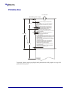
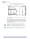
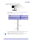
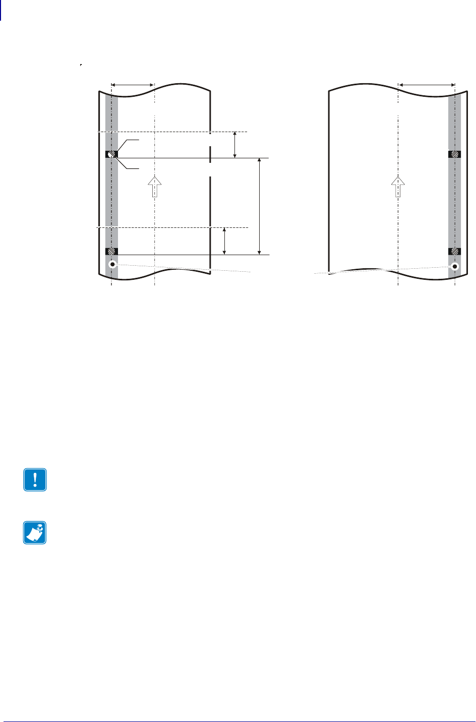
Figure 31 • Recommended Black Mark Size and Position
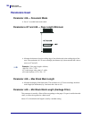
The sensor triggers on the black-to-white transition of the black-mark, which is when the black
print ends (trailing edge).
Since the same sensor is used for both paper end and black-mark detection, the printer must
know the length of the black-mark to avoid signaling end-of-paper when it detects a black-
mark. The default setting accepts black-marks in the range 3 –16 mm, and works perfectly
with the recommended black-mark length of 5 mm. Marks shorter than 3 mm are interpreted
as dirt, and marks longer than 16 mm as out-of-paper. You can change both these values by
changing the printer default settings.
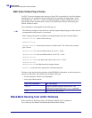
Black mark mode is selected by setting parameter 36 to 2, and storing the parameters.
Important • It is essential that you store the parameters in the printer for black mark
synchronization even if you enable black marks in the Windows driver. This is because
Windows is not used at paper loading, and feeding with the FF button on the printer.
Note • The Windows driver is not overwriting the black-mark related parameters since this is
done during the calibration process. Only Parameter 36 is changed in the driver.
Paper viewed from thermal-
coating side so black marks
are on opposite side
Min. page
length
(See specifi-
cations)
30 mm
Paper
feed
direction
Preprinting not
recommended
within this zone
Cut line
Cut line
25 mm
Black mark size 5 x 9 mm
25 mm
22 mm
Punched hole 5 mm
∅
Paper
feed
direction
or
58 and 60 mm paper 80 and 82.5 mm paper
C
L
C
L