


93
Default Parameter Settings
Print Setup
09/14/2009 TTP 2000 Technical Manual P1002902-002
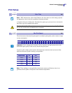
Calibrates the cut position. The value is a signed byte.
A change of 1 moves the cut 1/8 of a mm more than normal.
A change of –1 moves the cut 1/8 of a mm less than normal. -1 is entered as 256-1=255
The positive range is 1-127. The negative range is 128-255.
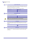
This parameter can be individually set for each printer and is not affected by the driver or reset
commands. It is used to compensate for differences in sensor position in production. After
moving or replacing the TOF-sensor, the calibration may have to be done again.
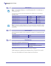
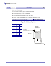
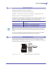
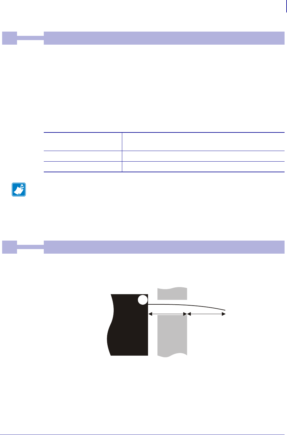
When the printout is printed and cut, the presenter ejects 50 mm of the page so that the
customer can take it. If the kiosk wall is thick, or if you just want a longer part of the printout
to be visible, this parameter adds extra eject length.
<ESC>&P<47><50> Adds 50 mm extra eject = 100 mm in total.
46
0Default
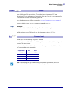
Cut Position Calibration
0 Min
255 Max
<ESC>&P<46><0> The cut is placed at the center of the sensor’s image of the
black-mark.
<ESC>&P<46><8> The paper is fed 1 mm extra before being cut.
<ESC>&P<46><248> The paper is fed 1 mm less before being cut.
Note • The cut is not 100% repetitive because the paper may be closer to the sensor for one
ticket than it is for the next. So do not expect a perfect synchronization between perforation
and cut.
It is better to cut slightly after a perforation than before because cutting before perforation
leaves a flap that is pushed through the printer and that may cause paper jam.
47
0Default
Wall Compensation (mm)
DRV
0 Min
255 Max
Kiosk
wall
n47
Eject n
Printer