


TELEDYNE API
Operating The M703E over the Serial I/O Ports M703E Calibrator Operator’s Manual
7.1.2. COMM PORT DEFAULT SETTINGS AND CONNECTOR PIN
ASSIGNMENTS
Received from the factory, the calibrator is set up to emulate an RS-232 DCE device.
RS-232 (COM1): RS-232 (fixed), DB-9 male connector.
o
Baud rate: 19200 bits per second (baud).
o
Data Bits: 8 data bits with 1 stop bit.
o
Parity: None.
COM2: RS-232 (configurable to RS 485), DB-9 female connector.
o
Baud rate: 115000 bits per second (baud).
o
Data Bits: 8 data bits with 1 stop bit.
o
Parity: None.
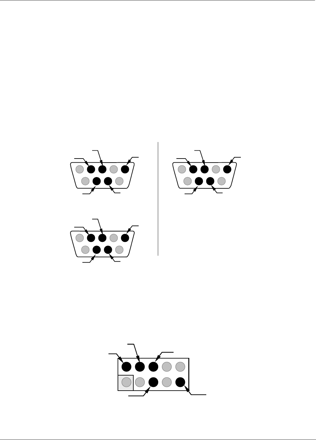
Male DB-9 (RS-232)
(As seen from outside analyzer)
(DTE mode)
(DCE mode)
1 2 3 4 5
6 7 8 9
RXD
GND
TXD
CTS
RTS
1 2 3 4 5
6 7 8 9
TXD
GND
RXD
RTS
CTS
Female DB-9 (COM2)
(As seen from outside analyzer)
(DTE mode)
1 234 5
6 789
RXD
GND
TXD
CTS
RTS
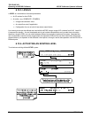
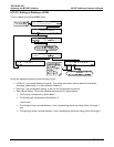
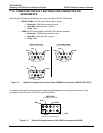
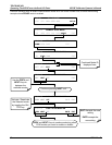
Figure 7-1: Default Pin Assignments for Back Panel COMM Port connectors (RS-232 DCE & DTE)
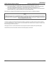
The signals from these two connectors are routed from the motherboard via a wiring harness to two 10-pin
connectors on the CPU card, CN3 (COM1) and CN4 (COM2).
CN3 & CN4
(Located on CPU card)
(As seen from inside analyzer)
TXD
GND
246810
135 7 9
RXD
RTS
CTS
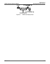
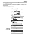
Figure 7-2: Default Pin Assignments for CPU COM Port connector (RS-232).
88 05744 Rev B