


TELEDYNE API
M703E Calibrator Operator’s Manual General Troubleshooting & Repair of the M703E Calibrator
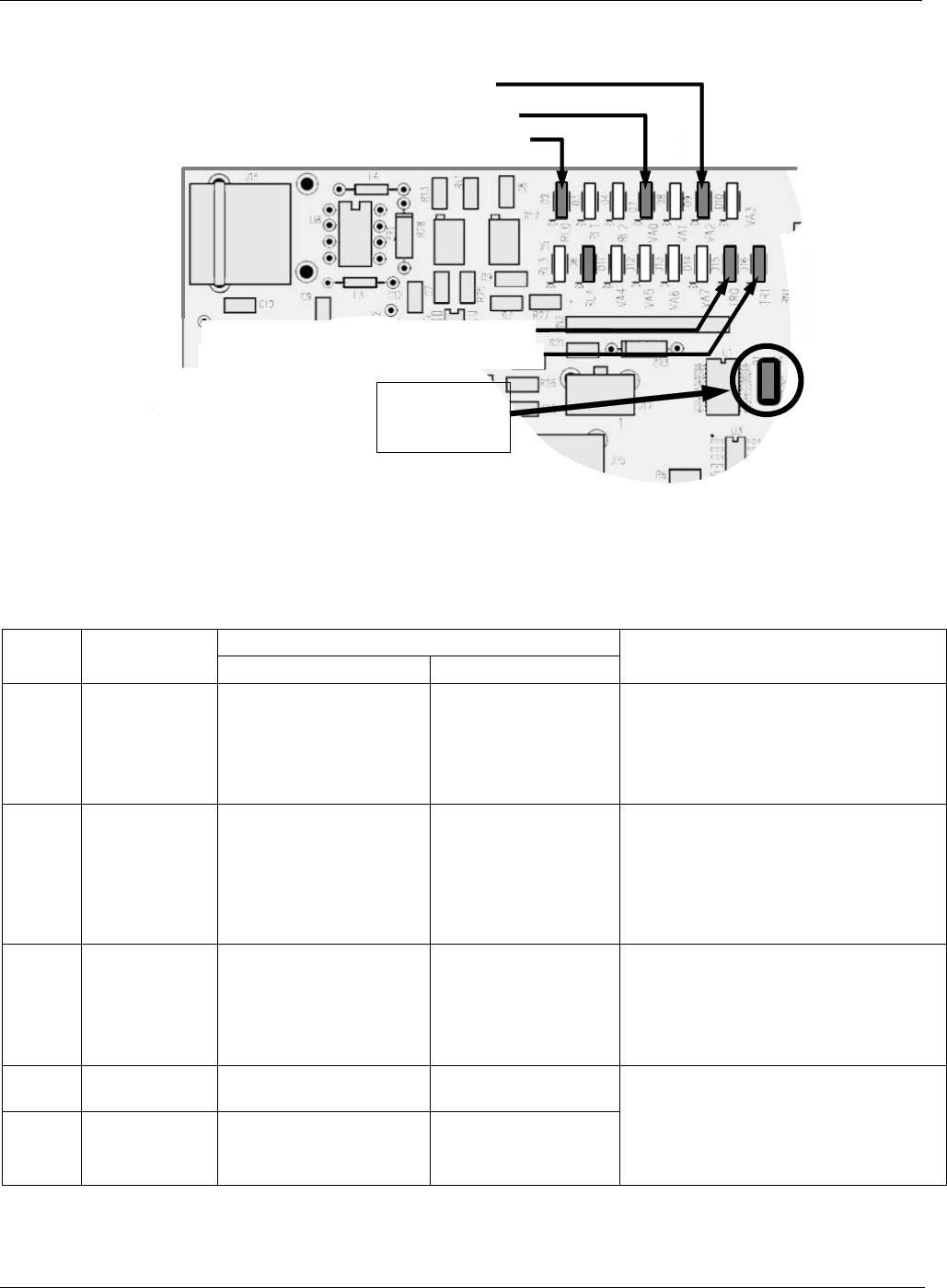
11.3.2.2. O
3
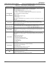
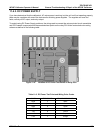
Status LEDs
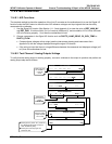
D15 (Yellow) - Photometer Lamp Heater
D16 (Yellow) – O
3
Generator Lamp Heater
D2 (Yellow) – Dry (zero) Air Pump Status
D9 (Green) – External Zero Air Valve Status
D1 (RED)
Watchdog
Indicator
D7 (Green) Photometer Meas/Ref Valve Status
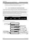
Figure 11-3: Relay PCA Status LEDS Used for Troubleshooting
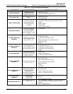
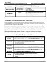
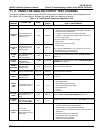
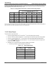
Table 11-5: Relay PCA Status LED Failure Indications
SIGNAL I/O PARAMETER
LED FUNCTION
ACTIVATED BY VIEW RESULT
DIAGNOSTIC TECHNIQUE
D2
Yellow
Status of AC
powered Dry
Air Pump
ZERO_AIR_PUMP
N/A
Pump should start /stop
Failed pump
Failed AC Relay on Relay PCA
Failed Relay PCA
Faulty AC Power Supply (PS2)
Faulty Connectors/Wiring
D7
Green
Photometer
Meas/Ref
Valve
PHOTO_REF_VALVE
N/A
Valve should audibly change states.
If not:
Failed Valve
Failed Relay Drive IC on Relay PCA
Failed Relay PCA
Faulty +12 VDC Supply (PS2)
Faulty Connectors/Wiring
D9
Green
Status of DC
powered
Photometer
Pump
O3-PUMP-ON
N/A
Pump should start /stop
Failed pump
Failed Drive IC on Relay PCA
Failed Relay PCA
Faulty AC Power Supply (PS2)
Faulty Connectors/Wiring
D15
Yellow
Photometer
Heater Status
PHOTO_LAMP_HEATER PHOTO_LAMP_TEMP
D16
Green
O
3
Generator
Heater Status
O3_GEN_HEATER O3_GEN_TEMP
Voltage displayed should change.
If not:
Failed Heater
Faulty Temperature Sensor
Failed AC Relay
Faulty Connectors/Wiring
05744 Rev B 185