


TELEDYNE API
General Troubleshooting & Repair of the M703E Calibrator M703E Calibrator Operators Manual
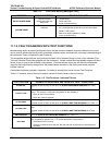
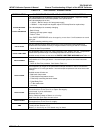
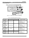
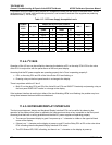
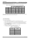
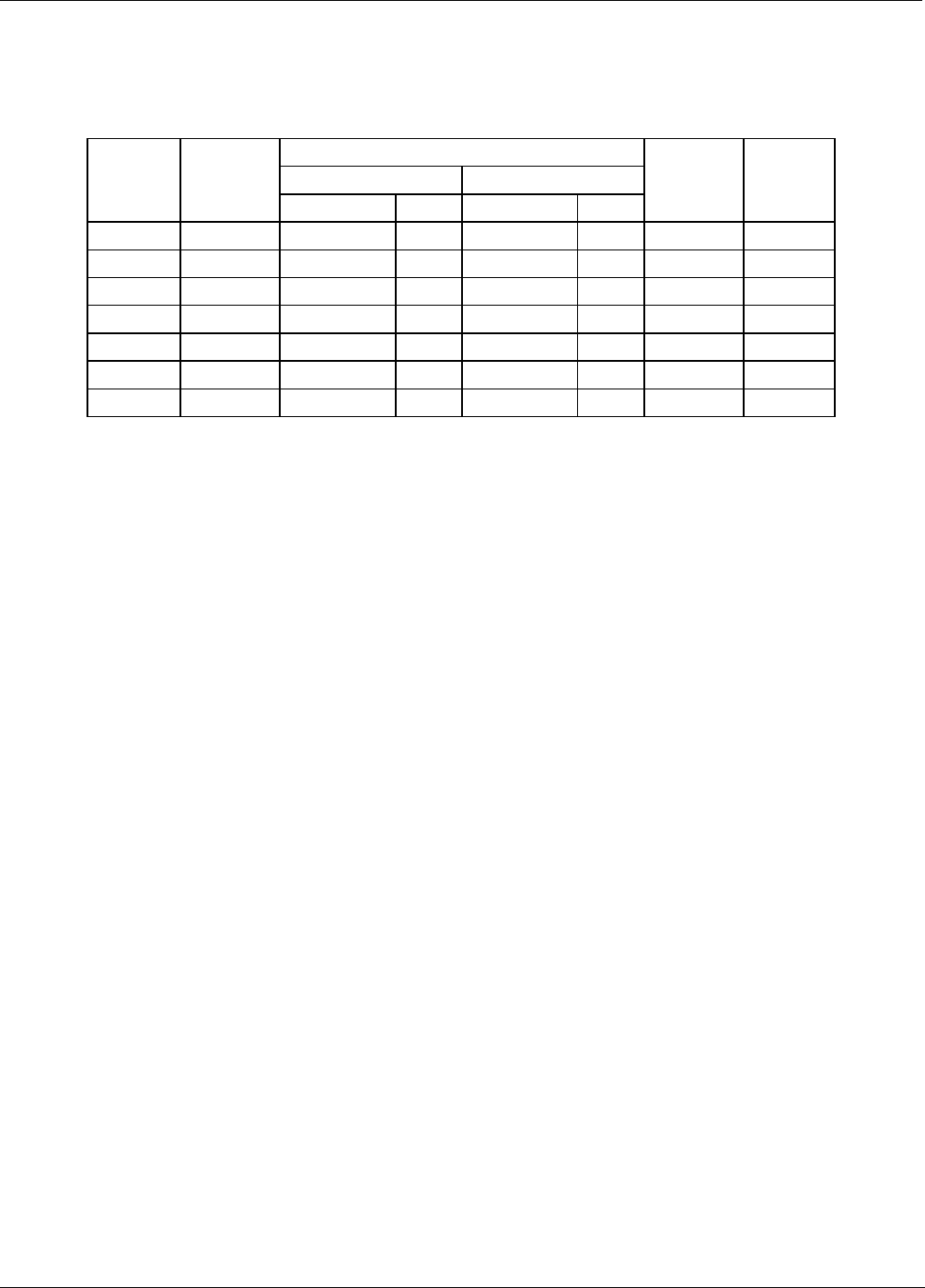
A voltmeter should be used to verify that the DC voltages are correct per the values in the table below, and an
oscilloscope, in AC mode, with band limiting turned on, can be used to evaluate if the supplies are producing
excessive noise (> 100 mV p-p).
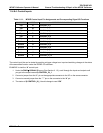
Table 11-7: DC Power Supply Acceptable Levels
CHECK RELAY PCA TEST POINTS
FROM TEST POINT TO TEST POINT
POWER
SUPPLY
ASSY
VOLTAGE
NAME # NAME #
MIN V MAX V
PS1 +5 Dgnd 1 +5 2 4.8 5.25
PS1 +15 Agnd 3 +15 4 13.5 16V
PS1 -15 Agnd 3 -15V 5 -14V -16V
PS1 Agnd Agnd 3 Dgnd 1 -0.05 0.05
PS1 Chassis Dgnd 1 Chassis N/A -0.05 0.05
PS2 +12 +12V Ret 6 +12V 7 11.75 12.5
PS2 +12 V ret +12V Ret 6 Dgnd 1 -0.05 0.05
11.4.4. I
2
C BUS
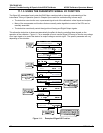
Operation of the I
2
C bus can be verified by observing the behavior of D1 on the relay PCA & D2 on the valve
driver PCA in conjunction with the performance of the front panel display.
Assuming that the DC power supplies are operating properly the I
2
C bus is operating properly if:
If D1 on the relay PCA and D2 of the Valve Driver PCA are flashing, or
Pressing a key on the front panel results in a change to the display.
There is a problem with the I
2
C bus if
Both D1 on the relay PCA and D2 of the Valve Driver PCA are ON/OFF Constantly and pressing a key on
the front panel DOES NOT results in a change to the display.
If the keyboard interface is working but either of the two Watchdog LEDs is not flashing, the problem may be a
wiring issue between the board and the motherboard
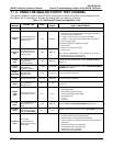
11.4.5. KEYBOARD/DISPLAY INTERFACE
The front panel keyboard, display and Keyboard Display Interface PCA can be verified by observing the
operation of the display when power is applied to the instrument and when a key is pressed on the front panel.
Assuming that there are no wiring problems and that the DC power supplies are operating properly:
The vacuum fluorescent display is good if on power-up a “-“ character is visible on the upper left hand
corner of the display.
If there is no “-“ character on the display at power-up and D1 on the Relay PCA or D2 on the valve driver
PCA is flashing then the Keyboard/Display Interface PCA is bad.
The CPU Status LED, DS5, is flashing, but there is no “-“ character on the display at power-up
188 05744 Rev B