


TELEDYNE API
M703E Calibrator Operator’s Manual Maintenance Schedule & Procedures
10.2. PERFORMING LEAK CHECKS
Leaks are the most common cause of analyzer malfunction; Section Error! Reference source not found.
presents a simple leak check procedure. Section 10.2.1 describes a more thorough procedure.
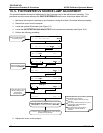
10.2.1. PRESSURE LEAK CHECK
- BEGINNING OF INSERTION: Replace original section below with this section, per Mike Troy:
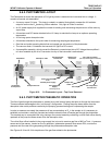
Obtain a leak checker similar to the Teledyne Instruments’ part number 01960, which contains a small pump,
shut-off valve and pressure gauge. Alternatively, a tank of pressurized gas, with the two-stage regulator
adjusted to ≤ 15 psi, a shutoff valve and pressure gauge may be used.
CAUTION
Once the fittings have been wetted with soap solution, do not apply a vacuum as this will
cause soap solution to be drawn into the instrument, contaminating it.
DO NOT EXCEED 15 PSI PRESSURE.
1. Turn OFF power to the calibrator.
2. Remove the instrument cover
3. Install a leak checker or tank of gas as described above on the “dry air in” port at the rear panel.
4. Install caps on the following fittings on the rear panel.
Exhaust
Vent
Internal Vent
Zero
Air Inlet
Both CALGAS OUT fittings
NOTE
The M703E calibrator cannot be leak checked with the pump in line due to internal leakage that normally
occurs in the pump.
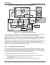
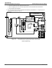
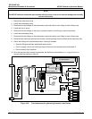
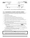
5. Locate the dry air pump.
6. Disconnect the two fittings on the dry air pump and install a union fitting in place of the pump.
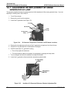
7. Locate the photometer pump.
8. Disconnect the two fittings on the photometer pump and install a union fitting in place of the pump.
9. Pressurize the calibrator with the leak checker, allowing enough time to pressurize the instrument fully.
10. Check each fitting with soap bubble solution, looking for bubbles.
05744 Rev B 167