


TELEDYNE API
Theory of Operation M703E Calibrator Operator’s Manual
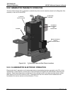
9.6.4. PHOTOMETER ELECTRONIC OPERATION
Photometer
Photometer
Lamp Heater
MOTHER BOARD
Photometer
Lamp Power
Supply
P
C
1
0
4
B
u
s
I
2
C Bus
Photometer
Pump
Thermistor Interface
Photometer
Detector
Preamp
A/D
Converter
RELAY PCA
I
2
C
Status
LED
y
PC 104
CPU Card
Disk on
Chip
Flash
Chip
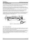
Absorption tube
Photometer
Detector
Photometer
Sample Gas
Pressure
Sensor
Photometer
UV Lamp
Temperature
Photometer
Sample Gas
Temperature
Photometer M/R
Valve
(Located on 0#
Generator Assembly)
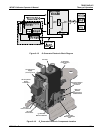
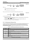
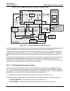
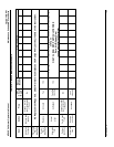
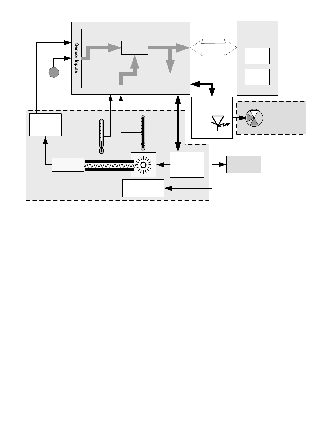
Figure 9-22: O
3
Photometer Electronic Block Diagram
Like the O
3
generator, the O
3
photometer and its subcomponents act as peripheral devices operated by the CPU
via the motherboard. Communications to and from the CPU are handled by the motherboard.
Outgoing commands for the various devices such as the photometer pump, the UV lamp power supply the U\V
Lamp heater are issued via the I
2
C bus to circuitry on the relay PCA which turns them ON/OFF. The CPU also
issues commands over the I
2
C bus that cause the relay PCA to cycle the measure/reference valve back and
forth.
Incoming date the UV light detector is amplified locally then converted to digital information by the motherboard.
Output from the photometers temperature sensors is also amplified and converted to digital data by the
motherboard. The O
3
concentration of the sample gas is computed by the CPU using this data (along with gas
pressure and flow data received from the M703E’s pressure sensors.
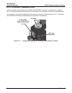
9.6.4.1. O
3
Photometer Temperature Control
In order to operate at peak efficiency the UV lamp of the M703E’s O
3
photometer is maintained at a constant
58ºC. This is intentionally set at a temperature higher than the ambient temperature of the M703E’s operating
environment to make sure that local changes in temperature do not affect the UV Lamp. If the lamp temperature
falls below 56ºC or rises above 61ºC a warning is issued by the calibrators CPU.
This temperature is controlled as described in the section on the relay PCA (Section 9.3.3.2).
The following TEST functions report these temperatures and are viewable from the instrument’s front panel:
PHOTO LAMP TEMP - The temperature of the UV Lamp reported in ºC.
PHOTO STEMP - The temperature of the Sample gas in the absorption tube reported in ºC.
160 05744 Rev B