


TELEDYNE API
M703E Calibrator Operator’s Manual Theory of Operation
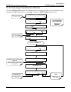
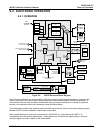
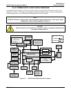
Finally, the CPU issues commands (also over the I2C bus) to a series of relays and switches located on a
separate printed circuit assembly, the relay board (located in the right rear of the chassis on its own mounting
bracket) to control the function of heaters and valves. The CPU includes two types of non-volatile data storage,
one disk-on-chip and one or two flash chips.
9.2.2.1. Disk On Chip
Technically, the disk-on-chip is an EEPROM, but appears to the CPU as, behaves as, and performs the same
functions in the system as an 8 mb disk drive, internally labeled as DOS drive C:\. It is used to store the
computer’s operating system files, the Teledyne Instruments firmware and peripheral files, and the operational
data generated by the calibrator’s internal data acquisition system.
9.2.2.2. Flash Chip
The flash chip is another, smaller EEPROM with about 64 kb of space, internally labeled as DOS drive B:\. The
M703E CPU board can accommodate up to two EEPROM flash chips. The M703E standard configuration is
one chip with 64 kb of storage capacity, which is used to store the calibrator configuration as created during final
checkout at the factory. Separating these data onto a less frequently accessed chip significantly decreases the
chance of data corruption through drive failure.
In the unlikely event that the flash chip should fail, the calibrator will continue to operate with just the DOC.
However, all configuration information will be lost, requiring the unit to be recalibrated.
05744 Rev B 139