


TELEDYNE API
M703E Calibrator Operator’s Manual Theory of Operation
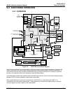
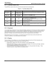
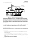
9.2.5. POWER SUPPLY AND CIRCUIT BREAKER
The M703E calibrator operates in two main AC power ranges: 100-120 VAC and 220-240 VAC (both ± 10%)
between 47 and 63 Hz. A 5 ampere circuit breaker is built into the ON/OFF switch. In case of a wiring fault or
incorrect supply power, the circuit breaker will automatically turn off the calibrator.
NOTE:
The M703E calibrator is equipped with a universal power supply that allows it to accept any AC power
configuration, within the limits specified in Table 2-2.
CAUTION
Should the power circuit breaker trip correct the condition causing this situation before
turning the calibrator back on.
RELAY PCA
SENSOR SUITES
LOGIC DEVICES
(e.g. CPU, I
2
C bus,
Keyboard, Display,
MotherBoard, etc.)
ON / OFF
SWITCH
PS 2
(+12 VDC)
Photometer
M/R valve
Cooling
Fan
PS 1
ANALOG SENSORS
O
3
Generator
Reference detector,
Photometer UV
Detector
Pre-Amplifiers
& Amplifiers
Sensor Control
& I/O Logic
Solenoid
Drivers
KEY
AC POWER
DC POWER
AC
POWER IN
+5 VDC
±15 VDC
O
3
Generator UV
Lamp Xfromer
Photometer
UV Lamp P/S
GAS
PRESSURE
SENSORS
GAS
TEMPERATURE
SENSORS
O
3
Generator UV
Lamp P/S
O
3
Generator
UV Lamp
Photometer
Pump
Controlled
via I
2
C
DRY AIR
Pump
AC
Relay
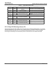
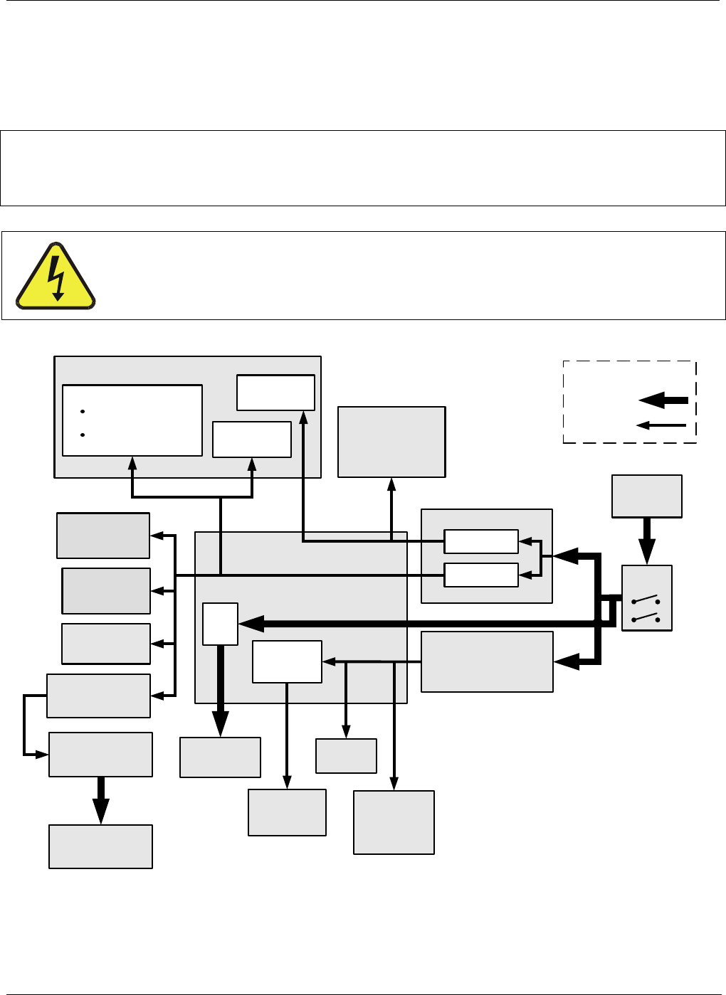
Figure 9-7: M703E Power Distribution Block diagram
05744 Rev B 145