


TELEDYNE API
Operating the M703E Calibrator M703E Calibrator Operator’s Manual
6.9. SETUP DIAG TEST CHAN OUTPUT: USING THE TEST
CHANNEL ANALOG OUTPUT
The M703E calibrator comes equipped with one analog output. It can be set by the user to carry the current
signal level of any one of the parameters listed in Table 6-8 and will output an analog VDC signal that rises and
falls in relations
hip with the value of the parameter.
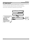
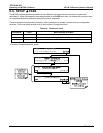
Pin-outs for the analog output connector at the rear panel of the instrument are:
ANALOG OUT
+
–
Figure 6-2: M703E the TEST CHANNEL Connector
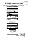
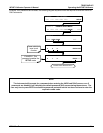
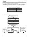
6.9.1. CONFIGURING THE TEST CHANNEL ANALOG OUTPUT
6.9.1.1. The Analog I/O Configuration Submenu.
Table 6-7 lists the analog I/O functions that are available in the M703E calibrator.
Table 6-7: DIAG - Analog I/O Functions
SUB MENU FUNCTION
AOUTS
CALIBRATED:
Shows the status of the analog output calibration (YES/NO) and initiates a calibration
of all analog output channels.
CAL_OUT_1:
CAL_OUT_2
NOT USED ON THE M703E
TEST OUTPUT Configures the 11 analog output:
RANGE
1
: Selects the DCV full-scale value of the output.
OVERRANGE: Turns the ± 5% over-range feature ON/OFF for this output channel.
REC_OFS
1
: Sets a voltage offset (not available when RANGE is set to CURRent loop.
AUTO_CAL
1
: Sets the channel for automatic or manual calibration
CALIBRATED
1
: Performs the same calibration as AOUT CALIBRATED, but on this
one channel only.
AIN CALIBRATED Shows the calibration status (YES/NO) and initiates a calibration of the analog to digital
converter circuit on the motherboard.
1
Changes to RANGE or REC_OFS require recalibration of this output.
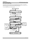
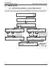
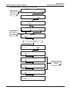
To configure the analyzer’s TEST CHANNEL, set the electronic signal type of each channel and calibrate the
outputs. This consists of:
10. Choosing a
TEST CHANNEL function to be output on the channel.
11. Selecting a signal level that matches the input requirements of the recording device attached to the
channel.
12. Determining if the over-range feature is needed and turn it on or off accordingly.
13. Adding a bipolar recorder offset to the signal if required (Section6.9.1.5).
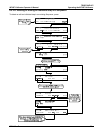
14.
Calib
rating the output channel. This can be done automatically or manually for each channel (see
Sections 6.9.2).
62 05744 Rev B