


TELEDYNE API
Theory of Operation M703E Calibrator Operator’s Manual
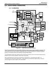
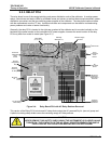
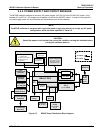
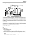
9.2.4.5. External Digital I/O
The external digital I/O performs two functions.
The
STATUS outputs carry logic-level (5V) signals through an optically isolated 8-pin connector on the rear
panel of the calibrator. These outputs convey on/off information about certain calibrator conditions such as
CONC VALID. They can be used to interface with certain types of programmable devices.
The
CONTROL outputs can be used to initiate actions by external peripheral devices in conjunction with
individual steps of a calibration sequence (see Section 6.5.1.6).
The
CONTROL inputs can be initiated by applying 5V DC power from an external source such as a PLC or data
logger (Section 6.5.1.5). Zero and span calibrations can be initiated by contact closures on the rear panel.
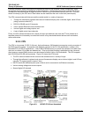
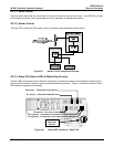
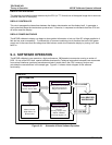
9.2.4.6. I
2
C Data Bus
I
2
C is a two-wire, clocked, digital serial I/O bus that is used widely in commercial and consumer electronic
systems. A transceiver on the motherboard converts data and control signals from the PC-104 bus to I
2
C. The
data are then fed to the keyboard/display interface and finally onto the relay board.
Interface circuits on the keyboard/display interface and relay board convert the I
2
C data to parallel inputs and
outputs. An additional interrupt line from the keyboard to the motherboard allows the CPU to recognize and
service key strokes on the keyboard.
9.2.4.7. Power-up Circuit
This circuit monitors the +5V power supply during calibrator start-up and sets the analog outputs, external digital
I/O ports, and I
2
C circuitry to specific values until the CPU boots and the instrument software can establish
control.
144 05744 Rev B