


TELEDYNE API
General Troubleshooting & Repair of the M703E Calibrator M703E Calibrator Operators Manual
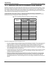
11.8. REPAIR PROCEDURES
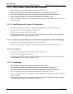
11.8.1. REPAIRING SAMPLE FLOW CONTROL ASSEMBLY
The critical flow orifice is housed in the flow control assembly (Teledyne Instruments part number: 001760400)
located on the top of the optical bench. A sintered filter protects the jewel orifice so it is unusual for the orifice to
need replacing, but if it does, or the filter needs replacement please use the following procedure (see the Spare
Parts list in Appendix B for part numbers and kits):
1. Turn off power to the calibrator.
2. Locate the assembly to be repaired, see Figure, 3–3.
3. Disconnect the pneumatic connection from the flow assembly.
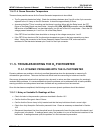
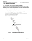
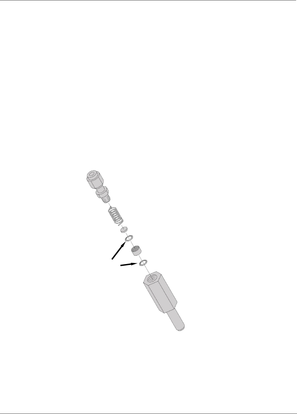
4. Remove the fitting and the components as shown in the exploded view in Figure 11.6.
5. Replace the o-rings (p/n OR000001) and the sintered filter (p/n FL000001).
6. If replacing the critical flow orifice itself (P/N 000941000), make sure that the side with the colored
window (usually red) is facing downstream to the gas flow.
7. Apply new Teflon
®
tape to the male connector threads
8. Re-assemble in reverse order.
Pneumatic Connector, Male 1/8”
(
P/N FT
_
70
Spring
(
P/N HW
_
20
)
Sintered Filte
r
(
P/N FL
_
01
)
Critical Flow Orifice
(P/N 000941000)
Make sure it is placed with the
jewel down)
O-Ring
(
P/N OR
_
01
)
Purge Housing
(
P/N 000850000
)
Figure 11-5: Critical Flow Restrictor Assembly Disassembly
202 05744 Rev B