


TELEDYNE API
M703E Calibrator Operator’s Manual Getting Started
3.2. ELECTRICAL CONNECTIONS
3.2.1. POWER CONNECTION
Verify the correct line voltage and frequency configuration on the serial number tag on the rear panel of the
M703E.
Attach the power cord to the calibrator and plug it into a power outlet capable of carrying at least 10 A current at
your AC voltage and that it is equipped with a functioning earth ground.
CAUTION
HIGH VOLTAGES ARE PRESENT INSIDE THE CALIBRATORS CASE
POWER CONNECTION MUST HAVE FUNCTIONING GROUND CONNECTION.
DO NOT DEFEAT THE GROUND WIRE ON POWER PLUG.
TURN OFF CALIBRATOR POWER BEFORE DISCONNECTING OR
CONNECTING ELECTRICAL SUBASSEMBLIES.
CAUTION
DO NOT LOOK AT THE PHOTOMETER UV LAMP.
UV LIGHT CAN CAUSE EYE DAMAGE.
ALWAYS WEAR GLASSES MADE FROM SAFETY UV FILTERING GLASS
(PLASTIC GLASSES WILL NOT DO).
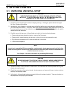
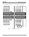
3.2.2. ANALOG OUTPUT TEST CHANNEL CONNECTIONS
The M703E is equipped with an analog output channel accessible through a connector on the back panel of the
instrument. The standard configuration for this output is 0-5 VDC. It can be set by the user to output one of a
variety of diagnostic test functions (see Section 6.9.)
To acce
ss these
signals attach a strip chart recorder and/or data-logger to the appropriate analog output
connections on the rear panel of the calibrator.
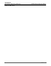
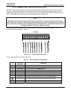
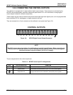
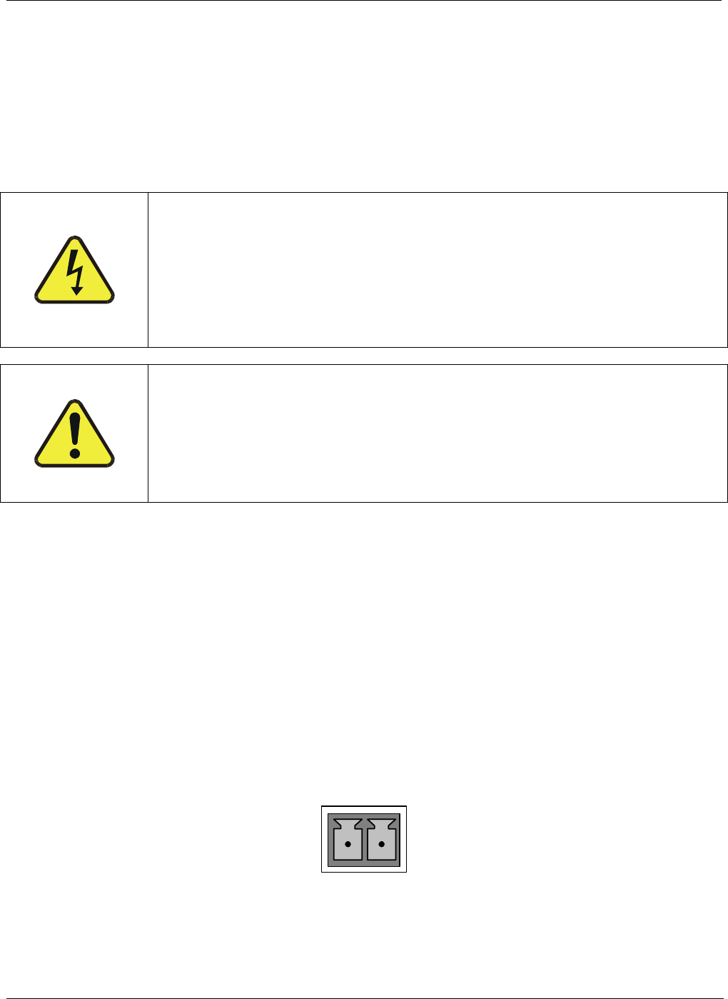
Pin-outs for the analog output connector at the rear panel of the instrument are:
ANALOG OUT
+
–
Figure 3-5: M703E the TEST CHANNEL Connector
05744 Rev B 13