


TELEDYNE API
Theory of Operation M703E Calibrator Operator’s Manual
9.2.6. AC POWER CONFIGURATION
The E-Series digital electronic systems will operate with any of the specified power regimes. As long as
instrument is connected to 100-120 VAC or 220-240 VAC at either 50 or 60 Hz it will turn on and after about 30
seconds show a front panel display. Internally, the status LEDs located on the Relay PCA, Motherboard and
CPU should turn on as soon as the power is supplied.
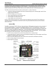
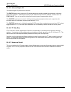
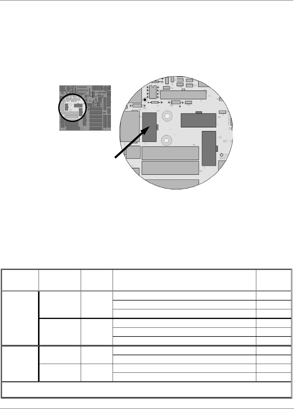
On the other hand, some of the calibrator’s the dry air pump must be properly configured for the type of power
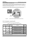
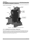
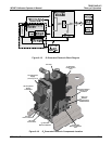
being supplied to the instrument. Figure 2-3 shows the location of the Pump AC Configuration jumper.
JP7
Pump
Configuration
Figure 9-8: Location of the AC Configuration Jumper for the Dry Air Pump
9.2.6.1. AC configuration – Internal Pump (JP7)
AC power configuration for the internal dry air pump is set using Jumper set JP7.
Table 9-2: AC Power Configuration for Internal Pumps (JP7)
LINE
POWER
LINE
FREQUENCY
JUMPER
COLOR
FUNCTION
JUMPER
BETWEEN
PINS
Connects pump pin 3 to 110 / 115 VAC power line 2 to 7
Connects pump pin 3 to 110 / 115 VAC power line 3 to 8
60 HZ WHITE
Connects pump pins 2 & 4 to Neutral 4 to 9
Connects pump pin 3 to 110 / 115 VAC power line 2 to 7
Connects pump pin 3 to 110 / 115 VAC power line 3 to 8
110VAC
115 VAC
50 HZ
1
BLACK
Connects pump pins 2 & 4 to Neutral 4 to 9
Connects pump pins 3 and 4 together 1 to 6
60 HZ BROWN
Connects pump pin 1 to 220 / 240VAC power line 3 to 8
Connects pump pins 3 and 4 together 1 to 6
220VAC
240 VAC
50 HZ
1
BLUE
Connects pump pin 1 to 220 / 240VAC power line 3 to 8
1
A jumper between pins 5 and 10 may be present on the jumper plug assembly, but is only functional on the M300E and
has no function on the Models M700E or M703E.
146 05744 Rev B