


TELEDYNE API
Maintenance Schedule & Procedures M703E Calibrator Operators Manual
NOTE
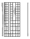
The M703E calibrator cannot be leak checked with the pump in line due to internal leakage that normally
occurs in the pump.
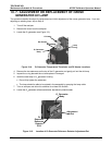
1. Remove the instrument cover
2. Locate the photometer pump.
3. Disconnect the two fittings on the photometer pump and install a union fitting in place of the pump.
4. Locate the dry air pump.
5. Disconnect the two fittings on the dry air pump and install a union fitting in place of the pump.
6. Locate the photometer pump.
7. Disconnect the two fittings on the photometer pump and install a union fitting in place of the pump.
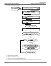
8. Pressurize the instrument with the leak checker, allowing enough time to pressurize the instrument fully.
9. Check each fitting with soap bubble solution, looking for bubbles.
Once the fittings have been wetted with soap solution.
Do not re-apply vacuum as it will draw soap solution into the instrument and contaminate it.
Do not exceed 15 psi pressure.
10. Once the leak has been located and repaired, the leak-down rate should be < 1 in-Hg (0.4 psi) in 5
minutes after the pressure is shut off.
PHOTOMETER
PRESSURE SENSOR
O
3
GEN / PHOTOMETER
PRESSURE / FLOW SENSOR PCA
O
3
GAS INPUT
PRESSURE SENSOR
O
3
FLOW
SENSOR
O
3
Generator Assembly
O
3
GENERATOR
Flow Control
(100 cm
3
/min)
REF/MEAS
Valve
On Back Panel
M703E Chassis
GAS OUTPUT MANIFOLD
PHOTOMETER
OUTLET
TO ANALYZER
VENT
TO ANALYZER
DRY AIR
IN
ZERO AIR
IN
PHOTOMETER
INLET
EXHAUST
PHOTOMETER
ZERO OUT
PHOTOMETER
ZERO IN
PHOTOMETER BENCH
PUMP
Flow Control
(800 cm
3
/min)
INTERNAL
VENT
Flow Control
(5.0 lpm)
Pressure
Regulator
Filter
PUMP
Flow Control
(1.0 to 2.0 LPM)
blk
CHARCOAL
SCRUBBER
blk
blu
blu
orn
orn
orn
orn
red
red
pur
pur
grn
grn
yel
yel
CAP
CAP CAP CAP
CAP
CAP
UNION
UNION
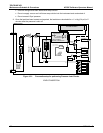
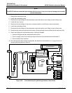
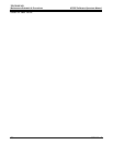
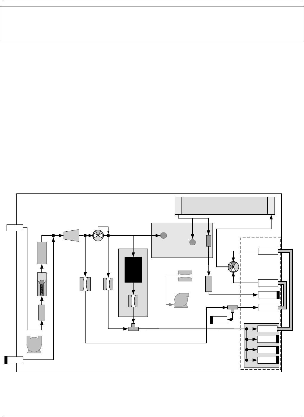
Figure 10-2: Pneumatic setup for performing Pressure Leak Checks
170 05744 Rev B