


TELEDYNE API
Operating The M703E over the Serial I/O Ports M703E Calibrator Operator’s Manual
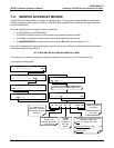
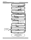
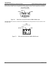
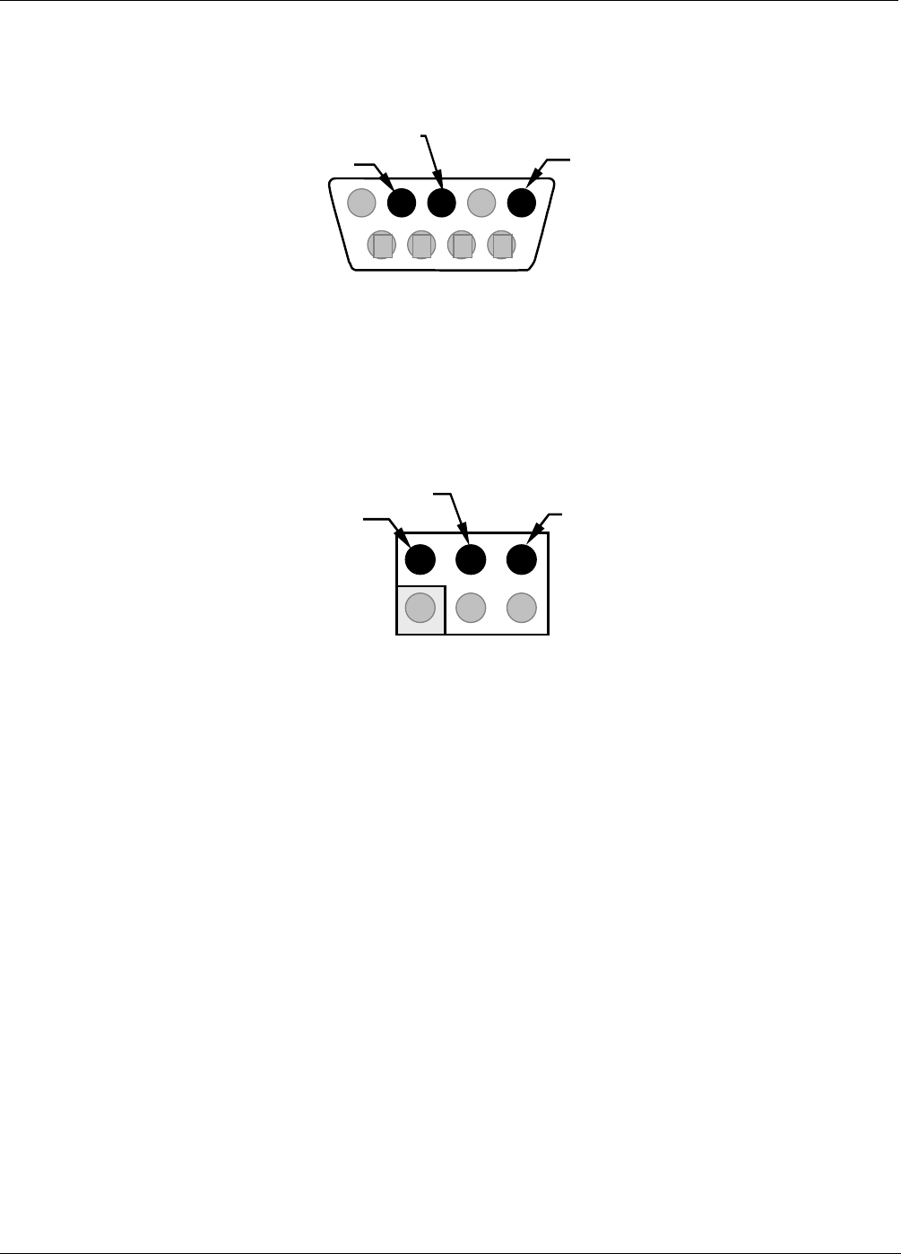
When COM2 is configured for RS-485 operation the port uses the same female DB-9 connector on the back of
the instrument as when Com2 is configured for RS-232 operation, however, the pin assignments are different.
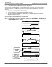
Female DB-9 (COM2)
(As seen from outside analyzer)
(RS-485)
1 234 5
6 7 8 9
GND
RX/TX
+
RX/TX
-
Figure 7-6: Back Panel connector Pin-Outs for COM2 in RS-485 mode.
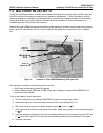
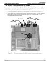
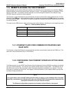
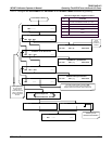
The signal from this connector is routed from the motherboard via a wiring harness to a 6-pin connector on the
CPU card, CN5.
CN5
(Located on CPU card)
(As seen from inside analyzer)
2 4 6
1 3 5
RX/TX
+
RX/TX
-
GND
Figure 7-7: CPU connector Pin-Outs for COM2 in RS-485 mode.
104 05744 Rev B