


TELEDYNE API
M703E Calibrator Operator’s Manual Theory of Operation
9.3.1.4. Keyboard/Display Interface Electronics
FRONT PANEL
Keypad
Decoder
Key Press
Detect
KEYBOARD
Beeper
Sample LED
(Green)
Cal LED
(Yellow)
Fault LED
(Red)
Display Data
Decoder
Display Power
Watchdog
From 5 VDC
Power Supply
I
2
C to Relay Board
Parallel Data
2 x 40 CHAR. VACUUM
FLUORESCENT DISPLAY
Display
Controller
Display Write
Clock
Serial
Data
I
2
C to/from CPU
Keyboard Interrupt Status Bit
I
2
C Interface
2
n
d
Lang.
Switch
Maint.
Switch
Optional
Maintenance
LED
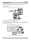
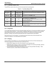
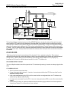
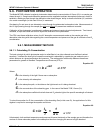
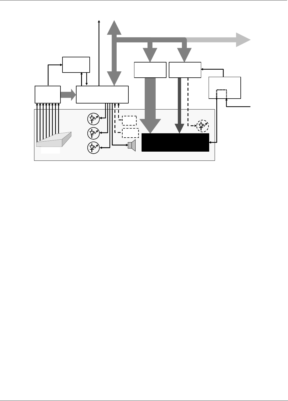
Figure 9-11: Keyboard and Display Interface Block Diagram
The keyboard/display interface electronics of the M703E Calibrator watches the status of the eight front panel
keys, alerts the CPU when keys are depressed, translates data from parallel to serial and back and manages
communications between the keyboard, the CPU and the front panel display. Except for the Keyboard interrupt
status bit, all communication between the CPU and the keyboard/display is handled by way of the instrument’s
I
2
C buss. The CPU controls the clock signal and determines when the various devices on the bus are allowed to
talk or required to listen. Data packets are labeled with addresses that identify for which device the information
is intended.
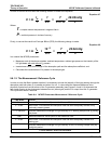
KEYPAD DECODER
Each key on the front panel communicates with a decoder IC via a separate analog line. When a key is
depressed the decoder chip notices the change of state of the associated signal; latches and holds the state of
all eight lines (in effect creating an 8-bit data word); alerts the key-depress-detect circuit (a flip-flop IC);
translates the 8-bit word into serial data and; sends this to the I
2
C interface chip.
KEY-PRESS DETECT CIRCUIT
This circuit flips the state of one of the inputs to the I
2
C interface chip causing it to send an interrupt signal to the
CPU
I
2
C INTERFACE CHIP
This IC performs several functions:
Using a dedicated digital status bit, it sends an interrupt signal alerting the CPU that new data from the
keyboard is ready to send.
Upon acknowledgement by the CPU that it has received the new keyboard data, the I
2
C interface chip
resets the key-depress-detect flip-flop.
In response to commands from the CPU, it turns the front panel status LEDs on and off and activates the
beeper.
Informs the CPU when the optional maintenance and second language switches have been opened or
closed (see Chapter 5 for information on these options).
05744 Rev B 149