


TELEDYNE API
Getting Started M703E Calibrator Operator’s Manual
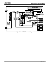
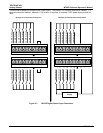
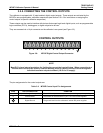
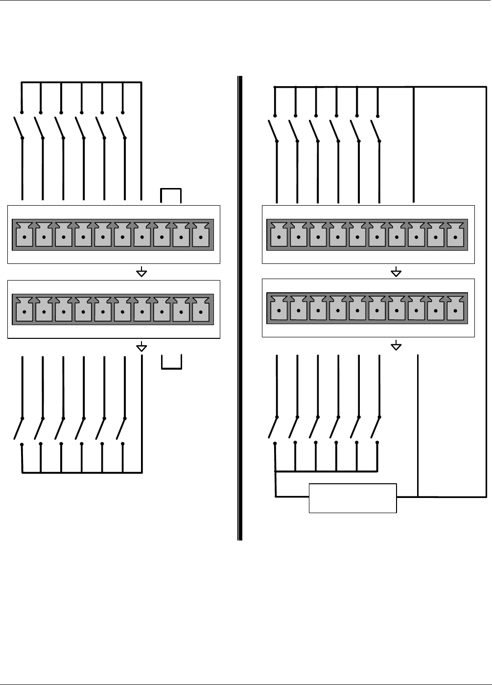
There are two methods for energizing the control inputs. The internal +5V available from the pin labeled “+” is
the most convenient method. However, if full isolation is required, an external 5 VDC power supply should be
used.
Example of Local Power Connections Example of External Power Connections
-
7 8 9 10 11 12 U +
CONTROL Bit-07
CONTROL Bit-08
CONTROL Bit-09
CONTROL Bit-10
CONTROL Bit-11
CONTROL Bit-12
+
5 VDC Power
Supply
7 8 9 10 11 12 U +
CONTROL Bit-07
CONTROL Bit-08
CONTROL Bit-09
CONTROL Bit-10
CONTROL Bit-11
1 2 3 4 5 6 U +
CONTROL Bit-01
CONTROL Bit-02
CONTROL Bit-03
CONTROL Bit-04
CONTROL Bit-05
1 2 3 4 5 6 U +
CONTROL Bit-01
CONTROL Bit-02
CONTROL Bit-03
CONTROL Bit-05
CONTROL Bit-06
CONTROL Bit-06
CONTROL Bit-04
CONTROL Bit-12
Figure 3-7: M703E Digital Control Input Connectors
16 05744 Rev B