


TELEDYNE API
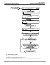
M703E Calibrator Operator’s Manual General Troubleshooting & Repair of the M703E Calibrator
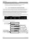
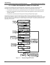
11.2. USING THE ANALOG OUTPUT TEST CHANNEL
The signals available for output over the M703E’s analog output channel can also be used as diagnostic tools.
See Section 6.9 for instruction on activating the analog output and selecting a
function.
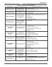
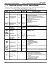
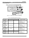
Table 11-3: Test Channel Outputs as Diagnostic Tools
TEST
CHANNEL
DESCRIPTION ZERO
FULL
SCALE
CAUSES OF EXTREMELY
HIGH / LOW READINGS
NONE
TEST CHANNEL IS TURNED OFF
O3 PHOTO
MEAS
The raw output of the
photometer during its
measure cycle
0 mV 5000 mV*
O3 PHOTO
REF
The raw output of the
photometer during its
reference cycle
0 mV 5000 mV
If the value displayed is:
- >5000 mV: The UV source has become brighter. Adjust the
UV Detector Gain potentiometer.
- < 100mV – Bad UV lamp or UV lamp power supply.
- < 2000mV – Lamp output has dropped, adjust UV Preamp
Board or replace lamp.
If the value displayed is constantly changing:
- Bad UV lamp.
- Defective UV lamp power supply.
- Failed I
2
C Bus.
If the PHOTO REFERENCE value changes by more than
10mV between zero and span gas:
-
Defective/leaking M/R switching valve.
O3 GEN
REF
The raw output of the
O
3
generator’s
reference detector
0 mV 5000 mV
Possible causes of faults are the same as
OUTPUT FLOW from
Table 11-2.
OUTPUT
FLOW
Output flow rate
(computed from
regulator pressure).
0 LPM 6.000 LPM
Possible causes of faults are the same as
O3 GEN REFERENCE
WARNING
from Table 11-1
SAMPLE
PRESSURE
The pressure of gas in
the photometer
absorption tube
0 "Hg 40 "Hg-In-A Check for Gas Flow problems.
SAMPLE
FLOW
The gas flow rate
through the photometer
0 cm
3
/min 1000 cc/m Check for Gas Flow problems.
SAMPLE
TEMP
The temperature of gas
in the photometer
absorption tube
0 C
70 C
Possible causes of faults are the same as
PHOTO STEMP from
Table 11-2
PHOTO
LAMP
TEMP
The temperature of the
photometer UV lamp
0 C
70 C
Possible failure of:
- Bench lamp heater
- Bench lamp temperature sensor
- Relay controlling the bench heater
- Entire Relay PCA
- I
2
C Bus
- Hot” Lamp
O3 LAMP
TEMP
The temperature of the
O
3
generator’s UV
lamp
0 mV 5000 mV Same as
PHOTO LAMP TEMP WARNING
from Table 11-1
CHASSIS
TEMP
The temperature inside
the M703E’s chassis
(same as
BOX TEMP)
0 C
70 C
Possible causes of faults are the same as
BOX TEMP from Table
11-2
O3 PHOTO
CONC
The current
concentration of O
3
being measured by the
photometer.
- - -
- I
2
C Bus malfunction
- Gas flow problem through the photometer.
- Electronic failure of the photometer subsystems
- Failure or pressure / temperature sensors associated with the
photometer
- Bad/incorrect Span Gas concentration
- Contamination of the Zero Air supply.
- Malfunction of the O
3
generator.
- Internal A/D converter problem
05744 Rev B 183