


TELEDYNE API
General Troubleshooting & Repair of the M703E Calibrator M703E Calibrator Operators Manual
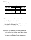
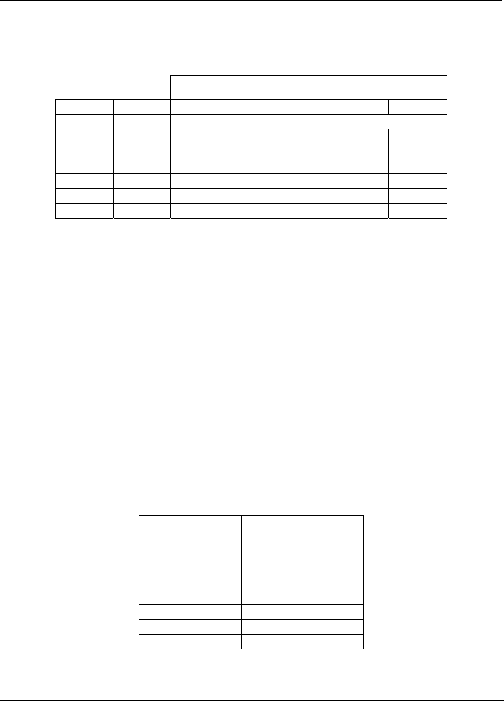
For each of the steps the output should be within 1% of the nominal value listed in the table below except for the
0% step, which should be within 0mV ±2 to 3 mV. Make sure you take into account any offset that may have
been programmed into channel (See Section 6.9.1.5).
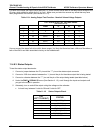
Table 11-9: Analog Output Test Function - Nominal Values Voltage Outputs
FULL SCALE OUTPUT OF VOLTAGE RANGE
(see Section 6.9.1.3)
100MV 1V 5V 10V
STEP % NOMINAL OUTPUT VOLTAGE
1 0 0 0 0 0
2 20 20 mV 0.2 1 2
3 40 40 mV 0.4 2 4
4 60 60 mV 0.6 3 6
5 80 80 mV 0.8 4 8
6 100 100 mV 1.0 5 10
If one or more of the steps fails to be within these ranges, it is likely that there has been a failure of the either or
both of the DACs and their associated circuitry on the motherboard.
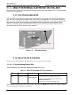
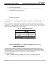
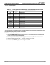
11.4.8.3. Status Outputs
To test the status output electronics:
1. Connect a jumper between the “D“ pin and the “” pin on the status output connector.
2. Connect a 1000 ohm resistor between the “+” pin and the pin for the status output that is being tested.
3. Connect a voltmeter between the “” pin and the pin of the output being tested (see table below).
4. Under the
DIAG SIGNAL I/O menu (See Section11.1.3), scroll through the inputs and outputs until
you get to the output in question.
5. Alternately, turn on and off the output noting the voltage on the voltmeter.
It should vary between 0 volts for ON and 5 volts for OFF.
Table 11-10: Status Outputs Check
PIN
(LEFT TO RIGHT)
STATUS
1
ST_SYSTEM_OK
2
SPARE
3
ST_CAL_ACTIVE
4
ST_DIAG_MODE
5
ST_TEMP_ALARM
6
ST_PRESS_ALARM
7 and 8
SPARE
192 05744 Rev B