


TELEDYNE API
Theory of Operation M703E Calibrator Operator’s Manual
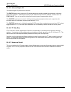
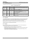
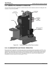
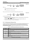
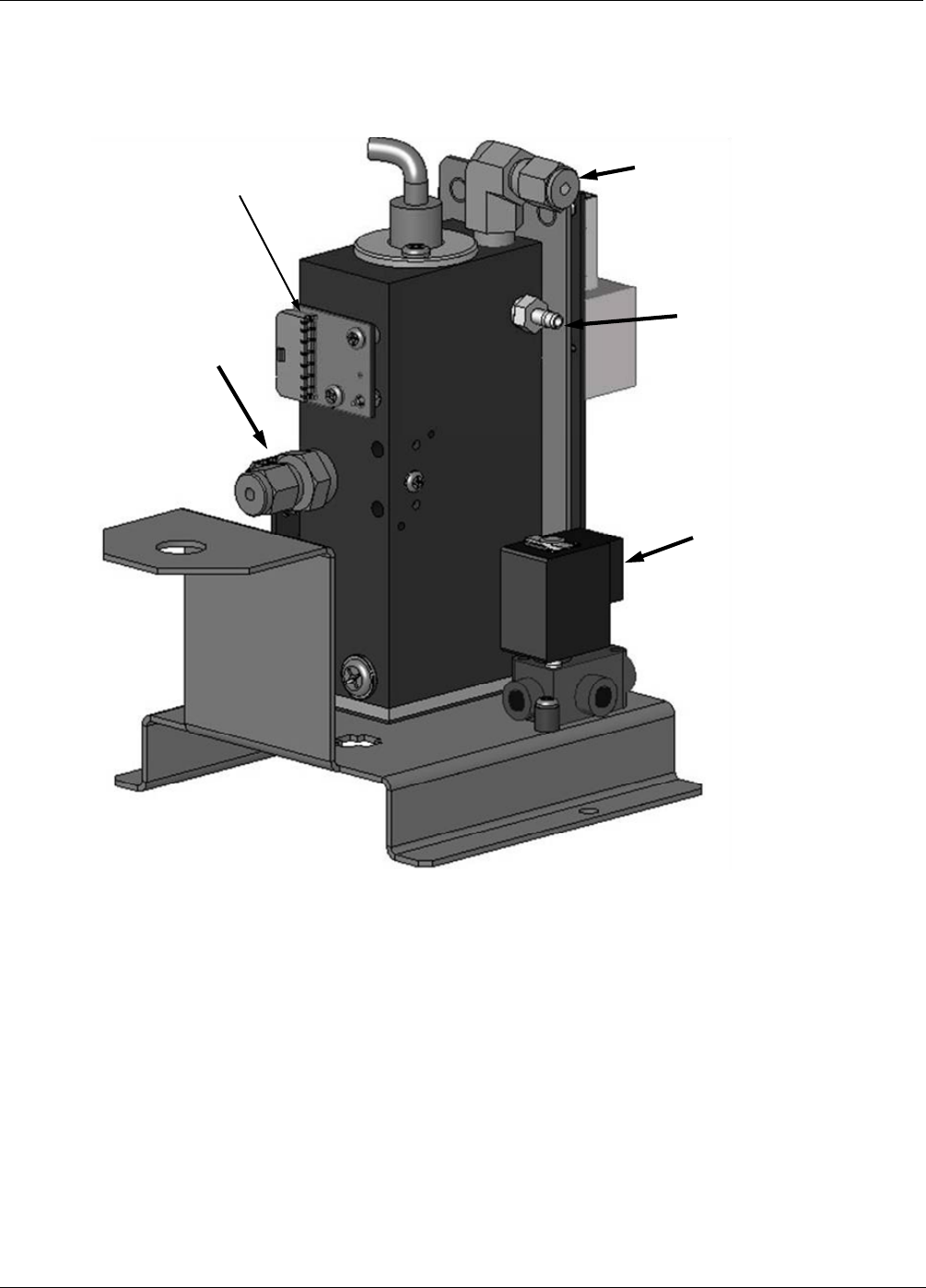
9.5.2. GENERATOR PNEUMATIC OPERATION
The rate of flow through the O
3
generator is controlled by a flow control assembly located on the Regulator Sub-
Assembly in the front of the M703E.
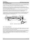
Measure / Reference
Valve for
Photometer Bench
O
3
Outlet to
Photometer
and
Internal Vent
O
3
Generator
Gas Inlet
O
3
Outlet
O
3
Generator
Heater Control PCA
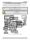
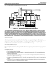
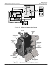
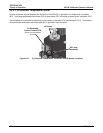
Figure 9-14: O
3
Generator Valve and Gas Fixture Locations
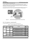
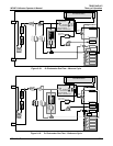
9.5.3. O
3
GENERATOR ELECTRONIC OPERATION
Electronically the O
3
generator and its subcomponents act as peripheral devices operated by the CPU via the
motherboard. Sensor signals, such as the UV lamp thermistor are routed to the motherboard, where they are
digitized. Digital data is sent by the motherboard to the calibrator’s CPU and where required stored in either
flash memory or on the CPU’s disk-on-chip. Commands from the CPU are sent to the motherboard and
forwarded to the various devices via the calibrator’s I
2
C bus.
152 05744 Rev B