


TELEDYNE API
M703E Calibrator Operator’s Manual General Troubleshooting & Repair of the M703E Calibrator
11.4.10. RS-232 COMMUNICATIONS
11.4.10.1. General RS-232 Troubleshooting
Teledyne Instruments calibrators use the RS-232 communications protocol to allow the instrument to be
connected to a variety of computer-based equipment. RS-232 has been used for many years and as equipment
has become more advanced, connections between various types of hardware have become increasingly difficult.
Generally, every manufacturer observes the signal and timing requirements of the protocol very carefully.
Problems with RS-232 connections usually center around four general areas:
Incorrect cabling and connectors. See Section 7.1.2 for connector and pin-out information.
The BAUD
rate and protocol are incorrectly configured. See Section 7.1.3.
If a modem is being u
sed, additional configuration and wiring rules must be observed. See Section 7.2
Incorre
ct setting of the DTE – DCE Switch is set correctly. See Section 7.1.1.
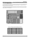
Verify that cable (03
596) that connects the serial COM ports of the CPU to J12 of the motherboard is
properly seated
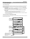
11.4.10.2. Troubleshooting Calibrator/Modem or Terminal Operation
These are the general steps for troubleshooting problems with a modem connected to a Teledyne Instruments
calibrator.
Check cables for proper connection to the modem, terminal or computer.
Check to make sure the DTE-DCE is in the correct position as described in Section 7.1.1.
Che
ck to make sure the set up command is correct (See Section 7.2)
Verify that th
e Ready to Send (RTS) signal is at logic high. The M703E sets pin 7 (RTS) to greater than 3
volts to enable modem transmission.
Make sure the BAUD rate, word length, and stop bit settings between modem and calibrator match, See
Section 7.1.3.
Use the
RS-232 test function to send “w” characters to the modem, terminal or computer; See Section
7.1.5
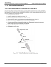
Get your term
inal, modem or computer to transmit data to the calibrator (holding down the space bar is
one way); the green LED should flicker as the instrument is receiving data.
Make sure that the communications software or terminal emulation software is functioning properly.
NOTE
Further help with serial communications is available in a separate manual “RS-232 Programming Notes”
Teledyne Instruments part number 013500000.
05744 Rev B 195