


TELEDYNE API
Theory of Operation M703E Calibrator Operator’s Manual
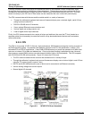
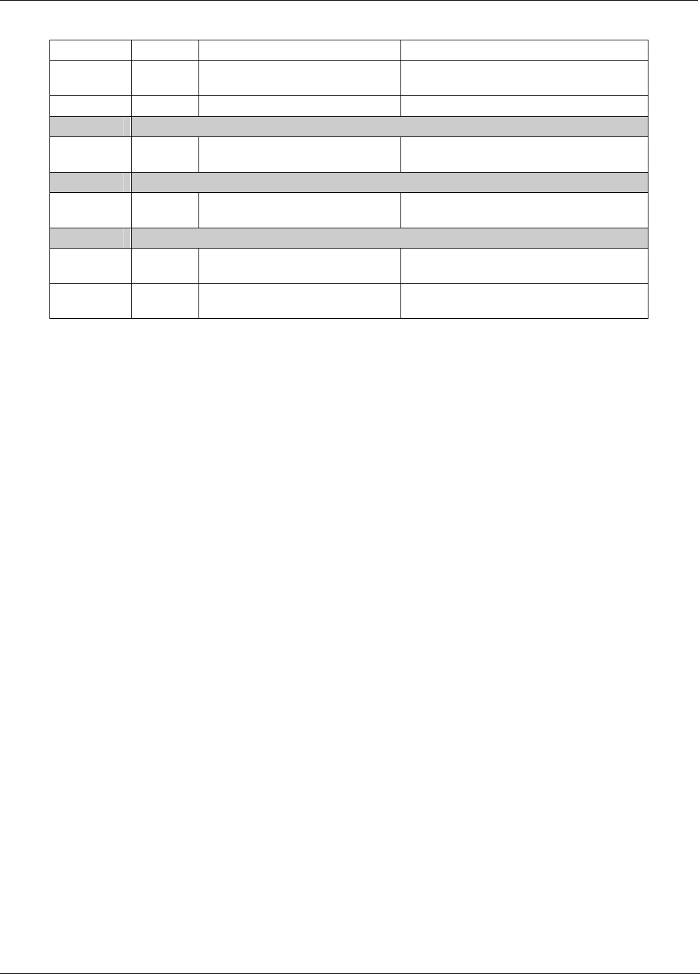
Table 9-1: Relay Board Status LEDs
LED COLOR DESCRIPTION FUNCTION
D1 Red
Watchdog Circuit; I
2
C bus
operation.
Blinks when I
2
C bus is operating properly
D2 Yellow Dry Air Pump Status When lit the zero air AC pump is running.
D3-6
SPARE
D7 Green Photometer Meas/Ref Valve
When lit the valve open to REFERENCE
gas path
D8
SPARE
D9 Green Ext. Zero Air valve Status
When lit the External Zero Air valve is
open
D10 - 14 SPARE
D15 Yellow Photometer Heater Status
When lit the photometer UV lamp heater
is on
D16 Yellow O
3
Generator Lamp Heater
When lit the O
3
generator UV lamp heater
is on
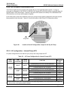
9.2.3.4. Relay PCA Watchdog Indicator (D1)
The most important of the status LEDs on the relay board is the red I
2
C Bus watchdog LED. It is controlled
directly by the calibrator’s CPU over the I
2
C bus. Special circuitry on the relay PCA watches the status of D1.
Should this LED ever stay ON or OFF for 30 seconds (indicating that the CPU or I
2
C bus has stopped
functioning) this Watchdog Circuit automatically shuts all valves and turns off all heaters and lamps.
142 05744 Rev B