EPSON Stylus Pro 7000 Revision B
Disassembly & Assembly Disassembly Flow 114
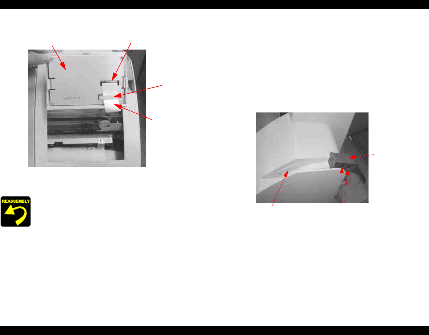
2. Remove the FFC cable from the connector and hook.
Figure 4-5. Panel Unit Removal 2/2
4.2.1.2 R Side Cover Removal
1. Remove the control panel unit as described in 4.2.1.1 “Panel Unit
Removal”.
2. Open the roll paper cover.
3. Push back the Paper Set Lever to the released position, remove two black
screws (CBP: M4x10) from the lever handle, and remove the handle.
4. Using a (-) driver or similar tool, remove the lever opening cap. The cap
may fall through the hole, so it is recommend you secure the cap between
your finger and the driver as you remove the cap.
Figure 4-6. Paper Set Lever Handle Removal
When replacing the control panel and FFC, make sure you push
the FFC cable slack inside and towards the rear of the printer
to avoid interfering with carriage movement.
Panel Unit
Connector
Hook
FFC
Lever opening cap
Two screws
Paper Set
Lever in
release
position


